
Datasheet


C2, C3, C4, and C
BYPASS
to maintain proper ratios
(C1 to other capacitors).
When using the minimum-required capacitor values,
make sure the capacitor value does not degrade exces-
sively with temperature. If in doubt, use capacitors with
a higher nominal value. The capacitor’s equivalent
series resistance (ESR), which usually rises at low tem-
peratures, influences the amount of ripple on V+ and V-.
Power-Supply Decoupling
In most circumstances, a 0.1µF bypass capacitor is
adequate. In applications that are sensitive to power-
supply noise, decouple V
CC
to ground with a capacitor
of the same value as charge pump capacitor C1.
Connect bypass capacitors as close to the IC as possible.
Transmitter Outputs when
Exiting Shutdown
Figure 2 shows two transmitter outputs when exiting
shutdown mode. As they become active, the two trans-
mitter outputs are shown going to opposite RS-232-
compatible levels (one transmitter input is high, the
other is low). Each transmitter is loaded with 3kΩ in par-
MAX3316–MAX3319
2.5V, 1µA, 460kbps,
RS-232-Compatible Transceivers
______________________________________________________________________________________ 11
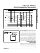
FORCEON
MASTER SHDN LINE
0.1µF1MΩ
FORCEOFF
MAX3318
MAX3319
POWER-
MANAGEMENT
UNIT
Figure 5. AutoShutdown Plus Initial Turn-On to Wake Up a
Mouse or Another System
V
CC
0
0
V+
V-
V
CC
0
INVALID
OUTPUT
READY
OUTPUT
TRANSMITTER
INPUTS
RECEIVER
INPUTS
}
INVALID
REGION
*MAX3318/MAX3319
TRANSMITTER
OUTPUTS
*V
CC
t
AUTOSHDN
t
WU
t
WU
t
INVL
t
INVH
t
AUTOSHDN
Figure 4b. AutoShutdown Plus,
INVALID
, and READY Timing Diagram