
Datasheet


MAX3291/MAX3292
% Jitter = (total jitter / t
BAUD
) · 100
When the total amount of time skew becomes 10% or
more of the baud period, the data error rate can
increase sharply.
128 Transceivers on the Bus
The standard RS-485 receiver input impedance is 12kΩ
(one unit load), and the standard driver can drive up to
32 unit loads. The MAX3291/MAX3292 transceivers have
a 1/4-unit-load receiver input impedance (48kΩ), allow-
ing up to 128 transceivers to be connected in parallel on
one communication line. Any combination of these
devices and/or other RS-485 transceivers with a total of
32 unit-loads or less can be connected to the line.
Low-Power Shutdown Mode
Initiate low-power shutdown mode by bringing RE high
and DE low. In shutdown the MAX3291/MAX3292 typi-
cally draw only 1µA of supply current.
Simultaneously driving RE and DE is allowed; the parts
are guaranteed not to enter shutdown if RE is high and
DE is low for less than 80ns. If the inputs are in this
state for at least 300ns, the parts are guaranteed to
enter shutdown.
Enable times t
ZH
and t
ZL
in the
Switching Characteris-
tics
tables correspond to when the part is not in the low-
power shutdown state. Enable times t
ZH(SHDN)
and
t
ZL(SHDN)
assume the parts are shut down. It takes dri-
vers and receivers longer to activate from the low-
power shutdown mode (t
ZH(SHDN)
, t
ZL(SHDN)
) than from
the driver/receiver disable mode (t
ZH
, t
ZL
).
Line Repeater
For line lengths greater than what one MAX3291/
MAX3292 can drive, use the repeater application
shown in Figure 17.
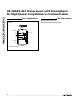
Figure 18 shows the system differential voltage for the
MAX3292 driving 4000 feet of 26AWG twisted-pair wire
into two 120Ω termination loads.
Line Termination
The MAX3291/MAX3292 are targeted for applications
requiring the best combination of long cable length and
lowest bit-error rate. In order to achieve this combina-
tion, the cable system must be set up with care. There
are three basic steps:
1) The cable should only have two ends (no tree configu-
ration with long branches), which are terminated with
a simple resistor termination whose value is the
cable’s characteristic impedance (Z
O
). Avoid termina-
tions anywhere else along the cable. This ensures that
there are no reflections at the end of the cable, and
that all transmitters (whether they are located at the
ends of the cable or somewhere along the length) see
the same impedance, equal to Z
O
/ 2.
2) Make all branches or stubs short enough so that
twice the propagation delay along the stub (down
and back) is significantly less than one baud period
(around 15% or less). This ensures that the reflec-
tions from the end of the stub (which are unavoid-
able, since the stubs are not terminated) settle in
much less than a baud period. If the application
requires a branch much longer than this, use a
repeater (see the
Line Repeater
section).
RS-485/RS-422 Transceivers with Preemphasis
for High-Speed, Long-Distance Communication
12 ______________________________________________________________________________________
Figure 17. Line-Repeater Application
2µs/div
V
A
- V
B
RO
DI
RECEIVER
INPUT
1V/div
5V/div
TYPICAL OPERATING CIRCUIT, R
PSET
= 1MΩ
5V/div
120Ω
120Ω
DATA IN
DATA OUT
R
D
RO
RE
DE
DI
A
B
Z
Y
MAX3291
MAX3292
Figure 18. MAX3292 System Differential Voltage Driving 4000
Feet, Using Two 120
Ω
Termination Resistors