
Datasheet


±15kV ESD-Protected, 1µA, 1Mbps 3.0V to 5.5V,
RS-232 Transceivers with AutoShutdown Plus
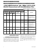
Pin Description (continued)
PIN
MAX3224E
MAX3225E
MAX3226E
MAX3227E
TQFN
DIP/
SSOP/
TSSOP
TQFN
SSOP/
TSSOP
MAX3244E
MAX3245E
SO/ SSOP/ TSSOP
MAX3245E
TQFN
NAME FUNCTION
12 14 9 12 23 25 FORCEON
Force-On Input, Active High.
Drive high to override
AutoShutdown Plus, keeping
transmitters and receivers on
(FORCEOFF must be high)
(Table 1).
16 18 11 14 25 27 GND Ground
17 19 12 15 26 29 V
CC
+3.0V to +5.5V Single Supply
Voltage
18 20 13 16 22 24 FORCEOFF
Force-Off Input, Active Low.
Drive low to shut down
transmitters, receivers
(except R2OUTB), and
charge pump. This overrides
AutoShutdown Plus and
FORCEON (Table 1).
— — — — 20 21 R2OUTB
TTL/CMOS Noninverting
Complementary Receiver
Outputs. Always active.
— — — — —
6, 10, 14,
18, 22, 28,
32, 36
N.C.
No Connection. Not internally
connected.
— — — — — — EP
Exposed Pad. Solder the
exposed pad to the ground
plane or leave unconnected.
_______________Detailed Description
Dual Charge-Pump Voltage Converter
The MAX3224E–MAX3227E/MAX3244E/MAX3245E’s
internal power supply consists of a regulated dual
charge pump that provides output voltages of +5.5V
(doubling charge pump) and -5.5V (inverting charge
pump), over the +3.0V to +5.5V range. The charge
pump operates in discontinuous mode: if the output
voltages are less than 5.5V, the charge pump is
enabled; if the output voltages exceed 5.5V, the
charge-pump is disabled. Each charge pump requires
a flying capacitor (C1, C2) and a reservoir capacitor
(C3, C4) to generate the V+ and V- supplies.
The READY output (MAX3224E–MAX3227E) is low
when the charge pumps are disabled in shutdown
mode. The READY signal asserts high when V- goes
below -4V.
8
Maxim Integrated
MAX3224E/MAX3225E/
MAX3226E/MAX3227E/MAX3244E/MAX3245E