
Datasheet


±15kV ESD-Protected, Down to 10nA, 3.0V to 5.5V,
Up to 1Mbps, True RS-232 Transceivers
Applications Information
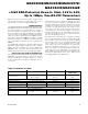
Capacitor Selection
The capacitor type used for C1–C4 is not critical for
proper operation; polarized or nonpolarized capacitors
can be used. The charge pump requires 0.1µF capaci-
tors for 3.3V operation. For other supply voltages, see
Table 2 for required capacitor values. Do not use val-
ues smaller than those listed in Table 2. Increasing the
capacitor values (e.g., by a factor of 2) reduces ripple
on the transmitter outputs and slightly reduces power
consumption. C2, C3, and C4 can be increased without
changing C1’s value. However, do not increase C1
without also increasing the values of C2, C3, C4,
and C
BYPASS
to maintain the proper ratios (C1 to
the other capacitors).
When using the minimum required capacitor values,
make sure the capacitor value does not degrade
excessively with temperature. If in doubt, use capaci-
tors with a larger nominal value. The capacitor’s equiv-
alent series resistance (ESR), which usually rises at low
temperatures, influences the amount of ripple on V+
and V-.
Power-Supply Decoupling
In most circumstances, a 0.1µF V
CC
bypass capacitor
is adequate. In applications sensitive to power-supply
noise, use a capacitor of the same value as charge-
pump capacitor C1. Connect bypass capacitors as
close to the IC as possible.
Operation Down to 2.7V
Transmitter outputs meet EIA/TIA-562 levels of ±3.7V
with supply voltages as low as 2.7V.
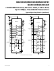
MAX3241E
EN
23
R5OUT
15
R4OUT
16
R3OUT
17
R2OUT
18
R1OUT
19
R2OUTB
20
R1OUTB
21
5kΩ
5kΩ
5kΩ
5kΩ
5kΩ
R5IN 8
V
CC
R4IN
7
6
R2IN 5
R1IN 4
SHDN
22
GND
25
T3IN
12
T2IN
13
T1IN
14
C2-
2
C2+
1
C1-
24
C1+
28
T3OUT
11
+V
COMPUTER SERIAL PORT
+V
-V
GND
Tx
T2OUT
10
T1OUT
9
V-
3
V+
27
V
CC
V
CC
C4
C3 C1
C2
C
BYPASS
V
CC
= +3.0V TO +5.5V
26
R3IN
MOUSE
Figure 6b. Mouse Driver Test Circuit
Maxim Integrated
13
MAX3222E/MAX3232E/MAX3237E/
MAX3241E/MAX3246E