
Datasheet


MAX3221/MAX3223/MAX3243
1µA Supply-Current, True +3V to +5.5V
RS-232 Transceivers with AutoShutdown
8 _______________________________________________________________________________________
other system to realize that the MAX3221/MAX3223/
MAX3243 is awake. If the other system outputs valid
RS-232 signals within that time, the RS-232 ports on
both systems remain enabled.
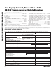
When shut down, the device’s charge pumps are turned
off, V+ decays to V
CC
, V- decays to ground, and the
transmitter outputs are disabled (high impedance). The
time required to exit shutdown is typically 100µs (Figure
5b).
Software-Controlled Shutdown
If direct software control is desired, INVALID can be
used to indicate DTR or Ring Indicator signal. Tie
FORCEOFF and FORCEON together to bypass Auto-
Shutdown so the line acts like a SHDN input.
___________Applications Information
Capacitor Selection
The capacitor type used for C1–C4 is not critical for
proper operation; either polarized or nonpolarized
capacitors may be used. The charge pump requires
0.1µF capacitors for 3.3V operation. For other supply
voltages, refer to Table 3 for required capacitor values.
Do not use values smaller than those listed in Table 3.
Increasing the capacitor values (e.g., by a factor of 2)
reduces ripple on the transmitter outputs and slightly
reduces power consumption. C2, C3, and C4 can be
increased without changing C1’s value. However, do
not increase C1 without also increasing the values
of C2, C3, and C4 to maintain the proper ratios (C1
to the other capacitors).
When using the minimum required capacitor values,
make sure the capacitor value does not degrade
excessively with temperature. If in doubt, use capaci-
tors with a larger nominal value. The capacitor’s equiva-
lent series resistance (ESR) usually rises at
low temperatures and influences the amount of ripple
on V+ and V-.
Table 2. AutoShutdown Logic
RS-232 SIGNAL
PRESENT AT
RECEIVER INPUT
FFOORRCCEEOOFFFF INPUT
FORCEON
INPUT
IINNVVAALLIIDD OUTPUT
TRANSCEIVER STATUS
Yes H X H Normal Operation
No H H L Normal Operation (Forced On)
No H L L Shutdown (AutoShutdown)
Yes L X H Shutdown (Forced Off)
No L X L Shutdown (Forced Off)
V-
V
CC
0
V+
0
V
CC
t
INVL
t
WU
INVALID
REGION
RECEIVER
INPUT
VOLTAGE
(V)
INVALID
OUTPUT
(V)
t
INVH
TRANSMITTERS ENABLED, INVALID HIGH
RECEIVER INPUT LEVELS
AUTOSHUTDOWN, TRANSMITTERS DISABLED,
1µA SUPPLY CURRENT, INVALID LOW
TRANSMITTERS ENABLED, INVALID HIGH
-2.7V
-0.3V
+2.7V
+0.3V
0V
INDETERMINATE
INDETERMINATE
(b)
(a)
Figure 5. AutoShutdown Trip Levels