
Datasheet


MAX3140
SPI/MICROWIRE-Compatible UART with Integrated
True Fail-Safe RS-485/RS-422 Transceivers
______________________________________________________________________________________ 11
Pin Description
UART Crystal Connection. Leave X2 unconnected for external clock. See the
Crystals,
Oscillators, and Ceramic Resonators
section.
X21 1
2
UART Crystal Connection. X1 also serves as an external clock input. See the
Crystals,
Oscillators, and Ceramic Resonators
section.
X12
3
4
UART Request-to-Send Active-Low Output. Controlled by the RTS bit. Use to control the dri-
ver enable in RS-485 networks.
RTS
4
UART Clear-to-Send Active-Low Input. Read via the CTS bit.
CTS
3
5
6 UART Asynchronous Serial-Data (transmitter) OutputTX6
7
8 GroundGND8
RS-485 Half/Full-Duplex Selector Pin. Connect H/F to V
CC
for half-duplex mode; connect H/F
to GND or leave it unconnected for full-duplex mode.
H/F
7
UART Asynchronous Serial-Data (receiver) Input. The serial information received from the modem
or RS-232/RS-485 receiver. A transition on RX while in shutdown generates an interrupt (Table 1).
RX5
9
10
RS-485 Receiver Output Enable. Drive RE low to enable RO; RO is high impedance when RE
is high. Drive RE high and DE low to enter low-power shutdown mode.
RE
10
11
12
RS-485 Driver Input. With DE high, a low on DI forces noninverting output low and inverting
output high. Similarly, a high on DI forces noninverting output high and inverting output low.
DI12
RS-485 Driver Output Enable. Drive DE high to enable driver outputs. These outputs are high
impedance when DE is low. Drive RE high and DE low to enter low-power shutdown mode.
DE11
13
14 No Connection. Not internally connected.N.C.14
15
— RS-485 Noninverting Driver OutputY16
RS-485 Transmitter Phase. Connect TXP to GND or leave it unconnected for normal transmit-
ter phase/polarity. Connect TXP to V
CC
to invert the transmitter phase/polarity.
TXP15
RS-485 Transceiver Slew-Rate-Limit Selector Pin. Connect SRL to GND for a 10Mbps com-
munication rate, connect SRL to V
CC
for a 500kbps rate, or leave SRL unconnected for a
115kbps rate.
SRL13
RS-485 Receiver Output. When RE is low and if A - B ≥ -50mV, RO will be high; if A - B ≤
-200mV, RO will be low.
RO9
16
17 No Connection. Not internally connected.N.C.17
—
18 RS-485 Inverting Receiver Input and RS-485 Inverting Driver Output*Z—
RS-485 Inverting Driver OutputZ18
—
19 RS-485 Receiver Input Resistors*B—
—
20 RS-485 Receiver Input Resistors*A—
RS-485 Noninverting Receiver InputA20
RS-485 Inverting Receiver InputB19
RS-485 Noninverting Receiver Input and RS-485 Noninverting Driver Output*Y—
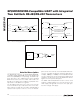
FULL
DUPLEX
HALF
DUPLEX
PIN
NAME FUNCTION