
Datasheet


Dual Serial UART with 128-Word FIFOs
MAX3109
17Maxim Integrated
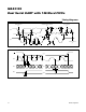
Figure 3. Transmit FIFO Signals
The contents of the TxFIFO and RxFIFO are both cleared
when the MODE2[1]: FIFORst bit is set high
.Transmitter Operation
Figure 3 shows the structure of the transmitter with the
TxFIFO. The transmit FIFO can hold up to 128 words of
data that are added by writing to the THR register.
The current number of words in the TxFIFO can be read
out by the host controller through the TxFIFOLvl regis-
ter. The transmit FIFO fill level can be programmed to
generate an interrupt when greater than or equal to a
programmed number of words are present in the TxFIFO
through the FIFOTrgLvl register. This TxFIFO interrupt
trigger level is selectable by the FIFOTrgLvl[3:0] bits.
When the transmit FIFO fill level increases to at least the
programmed trigger level, an interrupt is generated in
ISR[4]: TxTrigInt.
An interrupt is generated in ISR[5]: TFifoEmptyInt when
the transmit FIFO is empty. ISR[5] goes high when
the transmitter starts transmitting the last word in the
TxFIFO. An additional interrupt is generated in STSInt[7]:
TxEmptyInt when the transmitter completes transmitting
the last word.
To halt transmission, set the MODE1[1]: TxDisabl bit
high. After TxDisabl is set, the transmitter completes the
transmission of the current character and then ceases
transmission. Turn the transmitter off prior to enabling
auto software flow control and AutoRTS flow control.
The TX_ output logic can be inverted through the
IrDA[5]: TxInv bit. Unless otherwise noted, all transmitter
logic described in this data sheet assumes that TxInv is
set low.
Receiver Operation
The receiver expects the format of the data at RX_ to
be as shown in Figure 4. The quiescent logic state is
logic-high and the first bit (the START bit) is logic-low
(RxInv = 0). The 8-bit data word expected to be received
LSB first. The receiver samples the data near the midbit
instant (Figure 4). The received words and their associ-
ated errors are deposited into the receive FIFO. Errors
and status information are stored for every received word
(Figure 5). The host reads the data out of the receive
FIFO by reading RHR, which comes out oldest data first.
After a word is read out of RHR, LSR contains the status
information for that word.
Figure 4. Receive Data Format
CURRENT FILL LEVEL
TRANSMITTER TX_
TRANSMIT FIFO
FIFOTrgLvl[3:0]
TRIGGER
ISR[4]
THR
DATA FROM SPI/I
2
C INTERFACE
128
3
2
1
LEVEL
TxFIFOLvl
EMPTY
ISR[5]
RECEIVED DATA
NOTE: RxInv = 0.
LSB
START D0 D1 D2 D3 D4 D5 D6 D7 PARITY STOP STOP
MSB
MIDDATA
SAMPLING