
Datasheet


+5V-Powered, Multichannel RS-232
Drivers/Receivers
Supply Voltage Range
4.75 5.25
V
Transmitter Enable Time
MAX225 10 20
t
ET
No load
MAX244–MAX249 11 30
51030
MAX225 40
V
CC
Supply Current
(Normal Operation)
3kΩ loads on
all outputs
MAX244–MAX249 57
mA
Transition Slew Rate
825
C
L
= 50pF to 2500pF, R
L
= 3kΩ to 7kΩ, V
CC
= +5V,
T
A
= +25°C, measured from +3V to -3V or -3V to +3V
T
A
= T
MIN
to T
MAX
CONDITIONS
50
V/µs
MAX246–MAX249
(excludes charge-pump startup)
Shutdown Supply Current µA
5
t
PHLT
, Figure 1 1.3 3.5
µs
t
PLHT
, Figure 1 1.5 3.5
Transmitter Disable Time
Transmitter Propagation Delay
TLL to RS-232 (Normal Operation)
µs
t
DT
, Figure 4 100 ns
Transmitter + to - Propagation
Delay Difference (Normal Operation)
t
PHLT
- t
PLHT
UNITSMIN TYP MAX
350
PARAMETER
ns
Receiver + to - Propagation
Delay Difference (Normal Operation)
t
PHLR
- t
PLHR
350 ns
4.5 5.5MAX244–MAX249
MAX225
Leakage current ±1
Logic-low voltage 1.4 0.8
Control Input
Logic-high voltage 2.4 1.4
V
µA
T
A
= +25°C
t
PHLR
, Figure 2 0.6 1.5
t
PLHR
, Figure 2 0.6 1.5
Receiver Propagation Delay
TLL to RS-232 (Normal Operation)
µs
t
PHLS
, Figure 2 0.6 10
t
PLHS
, Figure 2 3.0 10
Receiver Propagation Delay
TLL to RS-232 (Low-Power Mode)
µs
Receiver-Output Enable Time t
ER
, Figure 3 100 500 ns
Receiver-Output Disable Time t
DR
, Figure 3 100 500 ns
MAX225/MAX245–MAX249
(includes charge-pump startup)
10 ms
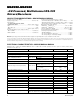
POWER SUPPLY AND CONTROL LOGIC
AC CHARACTERISTICS
Note 7: All units production tested at hot. Specifications over temperature are guaranteed by design.
Note 8: The 300Ω minimum specification complies with EIA/TIA-232E, but the actual resistance when in shutdown mode or V
CC
=
0V is 10MΩ as is implied by the leakage specification.
ELECTRICAL CHARACTERISTICS—MAX225/MAX244–MAX249 (continued)
(MAX225, V
CC
= +5.0V ±5%; MAX244–MAX249, V
CC
= +5.0V ±10%, external capacitors C1–C4 = 1µF; T
A
= T
MIN
to T
MAX
; unless
otherwise noted.) (Note 7)
Maxim Integrated
9
MAX220–MAX249
MAX220–MAX249