
Datasheet


MAX192
Low-Power, 8-Channel,
Serial 10-Bit ADC
______________________________________________________________________________________ 17
1 0 0
DIN
REFADJ
VREF
2.5V
0V
4V
0V
1 0 1 1 11 1 0 0 1 0 1
FULLPD FASTPD NOPD FULLPD FASTPD
2ms WAIT
COMPLETE CONVERSION SEQUENCE
t
BUFFEN
≈ 15µs
τ = RC = 20kΩ x C
REFADJ
(ZEROS)
CH1 CH7
(ZEROS)
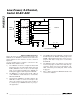
Figure 13. FULLPD/FASTPD Power-Up Sequence
RC filter with the internal 20kΩ reference resistor with a
0.2ms time constant. To achieve full 10-bit accuracy,
10 time constants or 2ms are required after power-up.
Waiting 2ms in FASTPD mode instead of full power-up
will reduce the power consumption by a factor of 10 or
more. This is achieved by using the sequence shown in
Figure 13.
Lowest Power at Higher Throughputs
Figure 14b shows the power consumption with
external-reference compensation in fast power-down,
with one and eight channels converted. The external
4.7µF compensation requires a 50µs wait after
power-up, accomplished by 75 idle clocks after a
dummy conversion. This circuit combines fast
multi-channel conversion with lowest power consump-
tion possible. Full power-down mode may provide
increased power savings in applications where the
1000
1
0 100 300 500
FULL POWER-DOWN
10
100
MAX192-14A
CONVERSIONS PER CHANNEL PER SECOND
200 400
2ms FASTPD WAIT
400kHz EXTERNAL CLOCK
INTERNAL COMPENSATION
8 CHANNELS
1 CHANNEL
AVG. SUPPLY CURRENT (µA)
10,000
10
0
FAST POWER-DOWN
100
1000
CONVERSIONS PER CHANNEL PER SECOND
8 CHANNELS
1 CHANNEL
4k 8k 12k 16k
2MHz EXTERNAL CLOCK
EXTERNAL COMPENSATION
50µs WAIT
AVG. SUPPLY CURRENT (µA)
MAX192-14B
3.0
2.5
2.0
1.5
1.0
0.5
0
0.0001 0.001 0.01 0.1 1 10
TIME IN SHUTDOWN (sec)
POWER-UP DELAY (ms)
Figure 14a. Supply Current vs. Sample Rate/Second, FULLPD,
400kHz Clock
Figure 14b. Supply Current vs. Sample Rate/Second, FASTPD,
2MHz Clock
Figure 14c. Typical Power-Up Delay vs. Time in Shutdown