9-1810; Rev 2; 12/03 KIT ATION EVALU E L B A AVAIL Dual, High-Efficiency, Step-Down Converter with Backup Battery Switchover Features The MAX1774 is a complete power-supply solution for PDAs and other hand-held devices. It integrates two high-efficiency step-down converters, a boost converter for backup battery regulation, and four voltage detectors in a small 32-pin QFN or 28-pin QSOP package. The MAX1774 accepts inputs from +2.7V to +28V and provides an adjustable main output from 1.25V to 5.
MAX1774 Dual, High-Efficiency, Step-Down Converter with Backup Battery Switchover ABSOLUTE MAXIMUM RATINGS IN, SHDNM, MDRV, DBI, LBI, ACI, CVH to GND .......................................................-0.3V to +30V IN to CVH, PDRV ......................................................-0.3V to +6V BIN to CS-.................................................................-0.3V to +6V LXB to GND ................................................-0.3V to (VBIN+ 0.7V) PDRV to GND.............................
Dual, High-Efficiency, Step-Down Converter with Backup Battery Switchover (Figure 1, VIN = VINS = +12V, VINC = VCS- = VCS+ = +3.3V, VCORE = +1.8V, TA = 0°C to +85°C, unless otherwise noted. Typical values are at TA = +25°C.) PARAMETER SYMBOL CONDITIONS MIN TYP MAX UNITS Maximum Duty Cycle 100 % Minimum On-Time 200 400 650 ns Minimum Off-Time 200 400 650 ns 5.5 V CORE REGULATOR Input Voltage Range VINC INC Undervoltage Lockout 2.6 VINC rising 2.40 2.47 2.55 VINC falling 2.30 2.
MAX1774 Dual, High-Efficiency, Step-Down Converter with Backup Battery Switchover ELECTRICAL CHARACTERISTICS (continued) (Figure 1, VIN = VINS = +12V, VINC = VCS- = VCS+ = +3.3V, VCORE = +1.8V, TA = 0°C to +85°C, unless otherwise noted. Typical values are at TA = +25°C.) PARAMETER SYMBOL CONDITIONS MIN TYP MAX UNITS 1.23 1.25 1.27 V 10 mV 5 mV REFERENCE Reference Voltage VREF Reference Load Regulation IREF = 0 to 50µA Reference Line Regulation VCS- = +2.5V to +5.
Dual, High-Efficiency, Step-Down Converter with Backup Battery Switchover (Figure 1, VIN = VINS = +12V, VINC = VCS- = VCS+ = +3.3V, VCORE = +1.8V, TA = 0°C to +85°C, unless otherwise noted. Typical values are at TA = +25°C.) PARAMETER SYMBOL SHDNM, SHDNC Input Low Current CONDITIONS SHDNM = SHDNC = GND SHDNC Input High Current V SHDNC = +5.
MAX1774 Dual, High-Efficiency, Step-Down Converter with Backup Battery Switchover ELECTRICAL CHARACTERISTICS (continued) (Figure 1, VIN = VINS = +12V, VINC = VCS+ = VCS- = +3.3V, VCORE = +1.8V, TA = -40°C to +85°C, unless otherwise noted.) (Note 2) PARAMETER SYMBOL CONDITIONS MIN MAX UNITS V CORE REGULATOR Input Voltage Range VINC INC Undervoltage Lockout 2.6 5.5 VINC rising 2.39 2.55 VINC falling 2.29 2.45 1.0 5.
Dual, High-Efficiency, Step-Down Converter with Backup Battery Switchover (Figure 1, VIN = VINS = +12V, VINC = VCS+ = VCS- = +3.3V, VCORE = +1.8V, TA = -40°C to +85°C, unless otherwise noted.) (Note 2) PARAMETER SYMBOL CONDITIONS MIN MAX UNITS ICVL = 50mA, VCS- = 0 2.6 3.1 V VCS- rising, hysteresis = 100mV typical 2.40 2.55 V CVL, CVH REGULATORS CVL Output Voltage VCVL CVL Switchover Threshold VIN = +4V, ICVH = 25mA CVH Output Voltage VIN - 2.
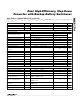
Typical Operating Characteristics (Circuit of Figure 1, VIN = +5V, VINC = +3.3V, TA = +25°C, unless otherwise noted.) CORE EFFICIENCY vs. LOAD 90 VIN = +12V 60 VIN = +15V 50 40 VIN = +18V 30 20 70 VIN = +2.7V 60 VIN = +3.3V 50 VIN = +5V 40 30 70 60 50 20 10 10 0 0 0 10 100 LOAD (mA) 1000 10,000 1 10 100 1000 VMAIN = 3.3V 0.01 0.1 LOAD (mA) 1 10 100 LOAD (mA) VREF ACCURACY vs. TEMPERATURE REFERENCE LOAD REGULATION 1.5 MAX1774-05 0 MAX1774-04 2.0 -0.2 -0.4 1.
Dual, High-Efficiency, Step-Down Converter with Backup Battery Switchover CORE SWITCHING WAVEFORMS (HEAVY LOAD 500mA) CORE SWITCHING WAVEFORMS (LIGHT LOAD 50mA) MAX1774-09 MAX1774-08 3.
MAX1774 Dual, High-Efficiency, Step-Down Converter with Backup Battery Switchover Typical Operating Characteristics (continued) (Circuit of Figure 1, VIN = +5V, VINC = +3.3V, TA = +25°C, unless otherwise noted.
Dual, High-Efficiency, Step-Down Converter with Backup Battery Switchover Pin Description (continued) NAME FUNCTION QSOP QFN — 10 LXB2 13 11 BIN 14 12 BKOFF Backup Disable Input. Driving BKOFF below +0.5V disables the backup mode. In backup mode, the device enters shutdown when this pin is pulled low. BKOFF can be driven from a digital signal or can be used as a low battery detector to disable the backup converter when the backup battery is low.
MAX1774 Dual, High-Efficiency, Step-Down Converter with Backup Battery Switchover NOTE: FOR INPUT VOLTAGES TO 28V SEE FIGURE 4 AND FIGURE 5 2.7V TO 5.5V D1 2.7V V IN_AC TO 5.5V MAIN BATTERY NSD03A10 C5 1µF NDS356AP P1 INS IN CVH R4 R1 C6 10µF MDRV P2 DBI PDRV ACI R2 FDS8928A L1 5µH RCS MAIN N1 LBI MAX1774 1MΩ R3 CMAIN 47µF NDRV 1.25V TO 5.5V PGND ON SHDNM CS+ ON SHDNC CS- OFF OFF BIN C1 10µF R10 D2 EP05Q 03L LXB FBM LXB2(QFN ONLY) L3 22µH BACKUP BATTERY 0.9V TO 5.
Dual, High-Efficiency, Step-Down Converter with Backup Battery Switchover MAX1774 TOFFMIN VMIN CS+ CS- TONMIN PON VVALLEY S FB PON VIN Q PSW REF R VCLM S VO Q NON NSW R VZERO NONOVERLAP PROTECTION Figure 2. Simplified Control System Block Diagram 100% duty cycle fail. Dropout voltage is defined as the difference between the input and output voltages when the input is low enough for the output to drop out of regulation.
MAX1774 Dual, High-Efficiency, Step-Down Converter with Backup Battery Switchover The MAX1774 features four separate current-limit threshold detectors and a watchdog timer for each of its step-down converters. In addition to the more common peak-current detector and zero-crossing detector, each converter also provides a valley-current detector, and a minimum-current detector.
Dual, High-Efficiency, Step-Down Converter with Backup Battery Switchover MAX1774 LBO LBO LBI 1.2V MDRV MDRV DBI DBO 1.2V BKUP BKUP ACI ACO INS NOAC 0.22V BKUP MODE BKOFF 0.5V CS- (MAIN OUT) BIN CS+ MAIN RDY CVL CS- CS+ IN RDY REF REF EN CVL PDRV MAIN BUCK CVH CVH FB SOFT-START NDRV ON PGND SHDNM SHDNC LXB2 (QFN ONLY) ON INC LXB BACKUP BOOST EN CORE BUCK LXC FB PGND FB PGNDC GND MAX1774 FBM FBC Figure 3.
MAX1774 Dual, High-Efficiency, Step-Down Converter with Backup Battery Switchover Place 1MΩ pullup resistors from the main output to ACO, LBO, and BKUP. Use a 1MΩ pullup resistor from MDRV to IN. When not in backup mode, the backup regulator is isolated from the main output by an internal switch. When the MAX1774 is in backup mode, the main converter is disabled, and the output of the backup regulator is connected to the main output. The core converter is still operable while in backup mode.
Dual, High-Efficiency, Step-Down Converter with Backup Battery Switchover D1 VIN_AC MAIN BATTERY 2.7V TO 20V NSD03A10 C5 1µF NDS356AP P1 1MΩ MAX1774 2.7V TO 28V IN ACI INS CVH R4 R1 C6 10µF MDRV P2 DBI FDS8928A L1 5µH PDRV R2 RCS MAIN N1 LBI CMAIN 47µF NDRV 2.6V TO 5.5V MAX1774 R3 PGND ON SHDNM CS+ ON SHDNC CS- OFF OFF BIN C1 10µF LXB LXB2 (QFN ONLY) FBM L3 22µH BACKUP BATTERY 0.9V TO 5.5V R10 D2 EP05 Q03L R11 BKOFF C2 10µF CVL R5 1MΩ ACO C3 1µF R6 1MΩ C4 0.
MAX1774 Dual, High-Efficiency, Step-Down Converter with Backup Battery Switchover 2.7V TO 28V D1 VIN_AC MAIN BATTERY 2.7V TO 20V NSD03A10 C5 NDS356AP IN INS CVH R4 P1 C6 10µF R1 MDRV P2 DBI FDS8928A L1 10µH PDRV R2 RCS MAIN N1 LBI ACI R3 CMAIN 47µF NDRV 2.6V TO 5.5V MAX1774 1MΩ PGND R12 ON SHDNM CS+ ON SHDNC CS- OFF OFF BIN D2 EP05 Q03L C1 10µF R10 LXB FBM LXB2 (QFN ONLY) L3 22µH R11 R13 R5 1MΩ BKOFF BACKUP BATTERY ACO C2 10µF 0.9V TO 5.
Dual, High-Efficiency, Step-Down Converter with Backup Battery Switchover Calculate the inductance value for either CORE or MAIN, LMIN : L(MIN) = (VIN - VOUT) ✕ (tON(MIN) / lRIPPLE) where tONMIN is typically 400ns, and lRIPPLE is the continuous conduction peak-to-peak lRIPPLE current. In continuous conduction, lRIPPLE should be chosen to be 30% of the maximum load current.
Dual, High-Efficiency, Step-Down Converter with Backup Battery Switchover 32, 44, 48L QFN.EPS MAX1774 Package Information PACKAGE OUTLINE 32,44,48L QFN, 7x7x0.90 MM 21-0092 H 1 2 U PACKAGE OUTLINE, 32,44,48L QFN, 7x7x0.
Dual, High-Efficiency, Step-Down Converter with Backup Battery Switchover QSOP.EPS PACKAGE OUTLINE, QSOP .150", .025" LEAD PITCH 21-0055 E 1 1 Maxim cannot assume responsibility for use of any circuitry other than circuitry entirely embodied in a Maxim product. No circuit patent licenses are implied. Maxim reserves the right to change the circuitry and specifications without notice at any time.