
Datasheet


Maxim Integrated
│
10
MAX17503 4.5V-60V, 2.5A, High-Efciency,
Synchronous Step-Down DC-DC Converter
With Internal Compensation
www.maximintegrated.com
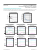
Pin Description
Pin Conguration
PIN NAME FUNCTION
1–3 V
IN
Power-Supply Input. 4.5V to 60V input supply range. Connect the V
IN
pinstogether.DecoupletoPGND
with a 2.2µF capacitor; place the capacitor close to the V
IN
andPGNDpins.RefertotheMAX17503EV
kit data sheet for a layout example.
4 EN/UVLO
Enable/Undervoltage Lockout. Drive EN/UVLO high to enable the output voltage. Connect to the center
of the resistor-divider between V
IN
andSGNDtosettheinputvoltageatwhichthedeviceturnson.Pull
up to V
IN
for always-on operation.
5
RESET
Open-Drain RESET Output. The RESET output is driven low if FB drops below 92% of its set value.
RESET goes high 1024 clock cycles after FB rises above 95% of its set value.
6 SYNC
Thedevicecanbesynchronizedtoanexternalclockusingthispin.SeetheExternal Frequency
Synchronization section for more details.
7 SS Soft-StartInput.ConnectacapacitorfromSStoSGNDtosetthesoft-starttime.
8 CF
Atswitchingfrequencieslowerthan500kHz,connectacapacitorfromCFtoFB.LeaveCFopenif
switchingfrequencyisequalormorethan500kHz.SeetheLoop Compensation section for more details.
9 FB
FeedbackInput.ConnectFBtothecentertapofanexternalresistor-dividerfromtheoutputtoGNDto
set the output voltage. See the Adjusting Output Voltage section for more details.
10 RT
ConnectaresistorfromRTtoSGNDtosettheregulator’sswitchingfrequency.LeaveRTopenforthe
default500kHzfrequency.SeetheSetting the Switching Frequency (RT) section for more details.
11 MODE
MODEpinconguresthedevicetooperateeitherinPWM,PFM,orDCMmodesofoperation.Leave
MODEunconnectedforPFMoperation(pulseskippingatlightloads).ConnectMODEtoSGNDfor
constant-frequency PWM operation at all loads. Connect MODE to V
CC
for DCM operation. See the
MODE Setting section for more details.
19
20
* EXPOSED PAD (CONNECT TO GROUND).
18
17
7
6
8
V
IN
RESET
9
V
IN
PGND
V
CC
MODE
PGND
12
LX
45
15 14 12 11
LX
BST
FB
CF
SS
SYNC
+
V
IN
SGND
3
13
LX
16
10
RT
PGND
TQFN
4mm × 4mm
MAX17503
TOP VIEW
EN/UVLO