
Datasheet


Setting the Valley Current Limit
The minimum current-limit threshold must be high
enough to support the maximum load current when the
current limit is at the minimum tolerance value. The val-
ley of the inductor current occurs at I
LOAD(MAX)
minus
half the ripple current; therefore:
where I
LIMIT(LOW)
equals the minimum current-limit
threshold voltage divided by the output sense element
(inductor DCR or sense resistor).
The four-level ILIM setting sets a valley current limit of
15mV, 30mV, 45mV, or 60mV across the CSH_ to CSL_
differential input.
Special attention must be made to the tolerance and
thermal variation of the on-resistance in the case of
DCR sensing. Use the worst-case maximum value for
R
DCR
from the inductor data sheet, and add some mar-
gin for the rise in R
DCR
with temperature. A good gen-
eral rule is to allow 0.5% additional resistance for each
°C of temperature rise, which must be included in the
design margin unless the design includes an NTC ther-
mistor in the DCR network to thermally compensate the
current-limit threshold.
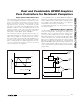
The current-sense method (Figure 14) and magnitude
determine the achievable current-limit accuracy and
power loss. The sense resistor can be determined by:
R
SENSE_
= V
LIM_
/I
LIMIT_
For the best current-sense accuracy and overcurrent
protection, use a 1% tolerance current-sense resistor
between the inductor and output as shown in Figure
14a. This configuration constantly monitors the inductor
current, allowing accurate current-limit protection.
However, the parasitic inductance of the current-sense
resistor can cause current-limit inaccuracies, especially
when using low-value inductors and current-sense
resistors. This parasitic inductance (L
ESL
) can be can-
celled by adding an RC circuit across the sense resis-
tor with an equivalent time constant:
Alternatively, low-cost applications that do not require
highly accurate current-limit protection can reduce the
overall power dissipation by connecting a series RC
circuit across the inductor (Figure 14b) with an equiva-
lent time constant:
and:
where R
CS
is the required current-sense resistance and
R
DCR
is the inductor’s series DC resistance. Use the
worst-case inductance and R
DCR
values provided by
the inductor manufacturer, adding some margin for the
inductance drop over temperature and load.
R
L
CRR
DCR
EQ
=×+
⎡
⎣
⎢
⎤
⎦
⎥
1
1
1
2
R
R
RR
R
CS DCR
=
+
2
12
CR
L
R
EQ EQ
ESL
SENSE
=
I
I
N
LIR
LIMIT LOW
LOAD MAX
PH
()
()
> −
⎛
⎝
⎜
⎞
⎠
⎟
1
2
MAX17007/MAX17008
Dual and Combinable QPWM Graphics
Core Controllers for Notebook Computers
______________________________________________________________________________________ 29
SENSE RESISTOR
L
MAX17007
MAX17008
C
OUT
INPUT (V
IN
)
C
IN
CSL_
CSH_
PGND
DL_
DH_
LX_
C
EQ
R
EQ
N
H
N
L
D
L
L
ESL
R
SENSE
C
EQ
R
EQ
=
L
ESL
R
SENSE
a) OUTPUT SERIES RESISTOR SENSING
Figure 14. Current-Sense Configurations (Sheet 1 of 2)