
Datasheet


(V+ = +4.5V to +5.5V, V
AGND
= V
PGND
= 0V; all voltages are measured with respect to PGND, unless otherwise noted. T
A
= T
J
=
-40°C to +125°C, unless otherwise noted. Typical values are at T
A
= +25°C.) (Notes 1, 5)
PARAMETER SYMBOL CONDITION MIN
TYP
MAX UNITS
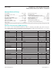
INTERFACE TIMING CHARACTERISTICS
CLK Clock Period t
CP
40 ns
CLK Pulse-Width High t
CH
19 ns
CLK Pulse-Width Low t
CL
19 ns
DIN Setup Time t
DS
4 ns
DIN Hold Time t
DH
8 ns
DOUT Propagation Delay t
DO
12 50 ns
DOUT Rise Time t
DR
C
DOUT
= 10pF, 20% to 80% 10 ns
DOUT Fall Time t
DF
C
DOUT
= 10pF, 80% to 20% 10 ns
LE Pulse-Width High t
LW
20 ns
LE Setup Time t
LS
15 ns
LE Rising to OUT_ Rising Delay t
LRR
(Note 6) 110 ns
LE Rising to OUT_ Falling Delay t
LRF
(Note 6) 325 ns
CLK Rising to OUT_ Rising Delay t
CRR
(Note 6) 110 ns
CLK Rising to OUT_ Falling Delay t
CRF
(Note 6) 325 ns
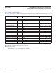
OE Rising to OUT_ Rising Delay
t
OER
(Note 6) 110 ns
OE Falling to OUT_ Falling Delay
t
OEF
(Note 6) 325 ns
OUT_ Turn-On Fall Time t
F
80% to 20% (Note 6) 210 ns
OUT_ Turn-Off Rise Time t
R
20% to 80% (Note 6) 130 ns
MAX16807 Integrated 8-Channel LED Driver with
Switch-Mode Boost and SEPIC Controller
www.maximintegrated.com
Maxim Integrated
│
5
5V Timing Characteristics