
Datasheet


MAX1652–MAX1655
High-Efficiency, PWM, Step-Down
DC-DC Controllers in 16-Pin QSOP
______________________________________________________________________________________ 19
output voltage as determined by the turns ratio is +15V,
the feedback resistor ratio should be set to produce
about +13.5V; otherwise, the SECFB one-shot might be
triggered unintentionally, causing an unnecessary
increase in supply current and output noise. In negative-
output (MAX1654) applications, the resistor-divider acts
as a load on the internal reference, which in turn can
cause errors at the main output. Avoid overloading REF
(see the Reference Load-Regulation Error vs. Load
Current graph in the
Typical Operating Characteristics
).
100kΩ is a good value for R3 in MAX1654 circuits.
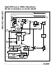
Output current on secondary winding applications is
limited at low input voltages. See the MAX1652
Maximum Secondary Output Current vs. Supply Voltage
graph in the Typical Operating Characteristics for data
from the application circuit of Figure 8.
Soft-Start Circuit (SS)
Soft-start allows a gradual increase of the internal cur-
rent-limit level at start-up for the purpose of reducing
input surge currents, and perhaps for power-supply
sequencing. In shutdown mode, the soft-start circuit
holds the SS capacitor discharged to ground. When
SHDN goes high, a 4µA current source charges the SS
capacitor up to 3.2V. The resulting linear ramp wave-
form causes the internal current-limit level to increase
proportionally from 0 to 100mV. The main output capaci-
tor thus charges up relatively slowly, depending on the
SS capacitor value. The exact time of the output rise
depends on output capacitance and load current and is
typically 1ms per nanofarad of soft-start capacitance.
With no SS capacitor connected, maximum current limit
is reached within 10µs.
Shutdown
Shutdown mode (SHDN = 0V) reduces the V+ supply
current to typically 3µA. In this mode, the reference and
VL are inactive. SHDN is a logic-level input, but it can
be safely driven to the full V+ range. Connect SHDN to
V+ for automatic start-up. Do not allow slow transitions
(slower than 0.02V/µs) on SHDN.
MAX1652
FB
GND
REF
SYNC
SECFB VL 10
2
11
7
35
14
Si9410
Si9410
D2
EC11FS1
T1 = TRANSPOWER TTI5870
* = OPTIONAL, MAY NOT BE NEEDED
16
15
13
D1
CMPSH
-3A
1N5819
12
8
9
V
IN
(6.5V TO 18V)
+15V AT
250mA
+5V
AT 3A
6
ON/OFF
1
CSL
CSH
BST
V+
DH
LX
DL
PGND
SHDN
SS
0.33µF
C2
4.7µF
C3
15µF
2.5V
220µF
10V
220µF
10V
0.1µF
22µF, 35V
22µF, 35V
0.01µF
20mΩ
22Ω*
4700pF*
T1
15µH
2.2:1
49.9k, 1%
210k, 1%
0.01µF
(OPTIONAL)
18V
1/4 W
C2
4.7µF
4
Figure 8. 5V/15V Dual-Output Application Circuit (MAX1652)