
Datasheet


MAX15023
Wide 4.5V to 28V Input, Dual-Output
Synchronous Buck Controller
16
Maxim Integrated
In case of a nonideal short circuit applied at the output,
the output voltage equals the output impedance times the
limited inductor current during this phase. After reaching
the maximum allowable limit of the soft-start duration
(twice the normal soft-start time), the controller remains off
for 7936 clock cycles before trying to soft-start again.
Undervoltage Lockout
The MAX15023 has an internal undervoltage lockout
(UVLO) circuit to monitor the voltage on V
CC
. The
UVLO circuit prevents the MAX15023 from operating if
the voltages for the MOSFET drivers or for the internal
control functions are too low. The V
CC
falling threshold
is 3.8V (typ), with 430mV hysteresis to prevent chatter-
ing on the rising/falling edge of the supply voltage.
Before V
CC
reaches UVLO rising threshold voltage,
DL_ and DH_ stay low to inhibit switching.
Thermal-Overload Protection
Thermal-overload protection limits total power dissipation
in the MAX15023. When the device’s die-junction tem-
perature exceeds T
J
= +150°C, an on-chip thermal sen-
sor shuts down the device, forcing DL_ and DH_ low,
allowing the IC to cool. The thermal sensor turns the
device on again after the junction temperature cools by
20°C. During thermal shutdown, the regulators shut
down, and soft-start is reset. Thermal-overload protection
can be triggered by power dissipation in the LDO regula-
tor, by excessive driving losses, or by both. Therefore,
carefully evaluate the total power dissipation (see the
Power Dissipation
section) to avoid unwanted triggering
of the thermal-overload protection in normal operation.
Design Procedure
Effective Input Voltage Range
Although the MAX15023 controllers can operate from
input supplies up to 28V and regulate down to 0.6V, the
minimum voltage conversion ratio (V
OUT
/V
IN
) might be
limited by the minimum controllable on-time. For proper
fixed-frequency PWM operation, the voltage conversion
ratio should obey the following condition:
where t
ON(MIN)
is 100ns (max) and f
SW
is the switching
frequency in Hertz. If the desired voltage conversion
does not meet the above condition, then pulse skipping
occurs to decrease the effective duty cycle. To avoid
this, decrease the switching frequency or lower the
input voltage V
IN
.
The maximum voltage conversion ratio is limited by the
maximum duty cycle (D
max
):
where V
DROP1
is the sum of the parasitic voltage drops
in the inductor discharge path, including synchronous
rectifier, inductor, and PCB resistances. V
DROP2
is the
sum of the voltage drops in the charging path, includ-
ing high-side switch, inductor, and PCB resistances. In
practice, the above condition should be met with ade-
quate margin for good load-transient response.
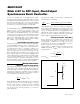
Setting the Enable Input (EN_)
Each controller has an enable input referenced to an
analog voltage (1.2V). When the voltage exceeds 1.2V,
the regulator is enabled. To set a specific turn-on
threshold that can act as a secondary UVLO, a resistive
divider circuit can be used (see Figure 2)
Select R
2
(EN_ to SGND resistor) to a value lower than
200kΩ. Calculate R
1
(V
MON
to EN_ resistor) with the fol-
lowing equation:
where V
EN_H_
= 1.2V (typical).
RR
V
V
MON
EN H
12
1=
⎛
⎝
⎜
⎞
⎠
⎟
⎡
⎣
⎢
⎢
⎤
⎦
⎥
⎥
−
__
V
V
D
D V (1 D ) V
V
OUT
IN
max
max DROP2 max DROP1
IN
<
×+ ×
−
−
V
V
tf
OUT
N
ON(MIN) SW
I
>×
EN_
R
1
V
MON
R
2
MA15023
Figure 2. Adjustable Enable Voltage