
Datasheet


Applications Information
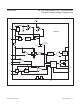
Setting the ON/OFF Threshold
When the voltage at ON/OFF rises above 1.225V, the
MAX15020 turns on. Connect a resistive divider from
IN to ON/OFF to GND to set the turn-on voltage (see
Figure 2). First select the ON/OFF to the GND resistor
(R2), then calculate the resistor from IN to ON/OFF (R1)
using the following equation:
IN
ON/OFF
V
R1 R2 1
V
=×−
where V
IN
is the input voltage at which the converter
turns on, V
ON/OFF
= 1.225V and R2 is chosen to be less
than 600kΩ.
If ON/OFF is connected to IN directly, the UVLO feature
monitors the supply voltage at IN and allows operation to
start when V
IN
rises above 7.2V.
Setting the Output Voltage
Connect a resistor-divider from OUT to FB to GND to
set the output voltage (see Figure 2). First calculate the
resistor (R7) from OUT to FB using the guidelines in the
Compensation Design section. Once R7 is known, calcu-
late R8 using the following equation:
OUT
FB
R7
R8
V
1
V
=
−
where V
FB
= REFIN and REFIN = 0 to 3.6V.
Setting the Output-Voltage Slew Rate
The output-voltage rising slew rate tracks the V
SS
slew
rate, given that the control loop is relatively fast compared
with the V
SS
slew rate. The maximum V
SS
upswing slew
rate is controlled by the soft-start current charging the
capacitor connected from SS to GND according to the
formula below:
OUT 7 8 SS 7 8 SS
8 8 SS
dV R R dV R R I
dt R dt R C
++
= ×=
when driving V
SS
with a slow-rising voltage source at
REFIN, V
OUT
will slowly rise according to the V
REFIN
slew rate.
The output-voltage falling slew rate is limited to the dis-
charge rate of C
SS
assuming there is enough load current
to discharge the output capacitor at this rate. The C
SS
discharge current is 15μA. If there is no load, then the
output voltage falls at a slower rate based upon leakage
and additional current drain from C
OUT
.
Inductor Selection
Three key inductor parameters must be specified for
operation with the MAX15020: inductance value (L), peak
inductor current (I
PEAK
), and inductor saturation current
(I
SAT
). The minimum required inductance is a function of
operating frequency, input-to-output voltage differential,
and the peak-to-peak inductor current (ΔI
L
). Higher ΔI
L
allows for a lower inductor value while a lower ΔI
L
requires
a higher inductor value. A lower inductor value minimizes
size and cost and improves large-signal and transient
response, but reduces efficiency due to higher peak cur-
rents and higher peak-topeak output voltage ripple for
the same output capacitor. Higher inductance increases
efficiency by reducing the ripple current. Resistive losses
due to extra wire turns can exceed the benefit gained from
lower ripple current levels especially when the inductance
is increased without also allowing for larger inductor
dimensions. A good compromise is to choose ΔI
P-P
equal
to 40% of the full load current.
Calculate the inductor using the following equation:
( )
IN OUT OUT
IN SW L
VV V
L
Vf I
−×
=
× ×∆
V
IN
and V
OUT
are typical values so that efficiency is
optimum for typical conditions. The switching frequency
(f
SW
) is fixed at 300kHz or 500kHz and can vary between
100kHz and 500kHz when synchronized to an external
clock (see the Oscillator/Synchronization Input (SYNC)
section). The peak-to-peak inductor current, which reflects
the peak-to-peak output ripple, is worst at the maximum
input voltage. See the Output Capacitor Selection section
to verify that the worst-case output ripple is acceptable.
The inductor saturating current (I
SAT
) is also important
to avoid runaway current during continuous output short
circuit. Select an inductor with an I
SAT
specification higher
than the maximum peak current limit of 4.5A.
MAX15020 2A, 40V Step-Down DC-DC Converter with
Dynamic Output-Voltage Programming
www.maximintegrated.com
Maxim Integrated
│
12