
Datasheet


MAX15018/MAX15019
125V/3A, High-Speed,
Half-Bridge MOSFET Drivers
_______________________________________________________________________________________
7
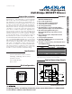
DELAY MATCHING (DH AND DL RISING)
MAX15018 toc18
10ns/div
V
IN_
10V/div
V
DH
AND V
DL
10V/div
C
L
= 0pF
RESPONSE TO V
DD
GLITCH
MAX15018 toc19
40
µ
s/div
V
DH_
V
IN_
V
DL
V
DD
10V/div
10V/div
10V/div
10V/div
Typical Operating Characteristics (continued)
(T
A
= +25°C, unless otherwise noted.)
_______________________________________________________________________________________
7
Pin Description
PIN NAME FUNCTION
1V
DD
Input Supply Voltage. Valid supply voltage ranges from 8V to 12.6V. Bypass V
DD
to GND with a parallel
combination of 0.1µF and 1µF ceramic capacitors as close to the IC as possible.
2 BST
Boost Flying Capacitor Connection. Connect a 0.22µF ceramic capacitor from BST to HS as close to the IC
as possible for the high-side MOSFET driver supply.
3 DH High-Side Gate Driver Output. Driver output for the high-side MOSFET gate.
4 HS Source Connection for High-Side MOSFET. Also serves as the return for the high-side driver.
5 IN_H High-Side Noninverting Logic Input
6 IN_L Low-Side Noninverting (MAX15018A/MAX15019A) or Low-Side Inverting (MAX15018B/MAX15019B) Input
7 GND
Ground. Use GND as a return path to the DL driver output and the IN_H, IN_L inputs. Must be connected to
ground.
8 DL Low-Side Gate Driver Output. Driver output for the low-side MOSFET gate.
—EP
Exposed Pad. Internally connected to GND. Externally connect the exposed pad to a large ground plane to
aid in heat dissipation. Grounding EP does not substitute the requirement to connect GND to ground.