
Datasheet


MAX1497/MAX1499
3.5- and 4.5-Digit, Single-Chip ADCs with LED
Drivers and µC Interface
18 ______________________________________________________________________________________
bits have been transferred (8 or 16). Once this has
occurred, the MAX1497/MAX1499 wait for the next
command byte. CS must not go high between data
transfers. If CS is toggled before the end of a write or
read operation, the device mode may be unknown.
Clock in 32 zeros to clear the device state and reset the
interface so it is ready to receive a new command byte.
On-Chip Registers
The MAX1497/MAX1499 contain 12 on-chip registers.
These registers configure the various functions of the
device and allow independent reading of the ADC
results and writing to the LED display. Table 5 lists the
address and size of each register.
The first of these registers is the status register. The 8-
bit status register contains the status flags for the ADC.
The second register is the 16-bit control register. This
register sets the LED display controls, range modes,
power-down modes, offset calibration, and the reset
register function (CLR). The third register is the 16-bit
overrange register, which sets the overrange limit of the
analog input. The fourth register is the 16-bit under-
range register, which sets the underrange limit of the
analog input. Registers 5 through 7 contain the display
data for the individual segments of the LED. The eighth
register contains the custom offset value. The ninth reg-
ister contains the 16 MSBs of the ADC conversion
result. The 10th register contains the LED data. The
11th register contains the peak analog input value. The
last register contains the lower four LSBs of the 20-bit
ADC conversion result.
REGISTER
N0.
ADDRESS
RS [4:0]
NAME WIDTH ACCESS
1 00000 Status register 8 Read only
2 00001 Control register 16 R/W
3 00010 Overrange register 16 R/W
4 00011 Underrange register 16 R/W
5 00100 LED segment-display register 1 16 R/W
6 00101 LED segment-display register 2 16 R/W
7 00110 LED segment-display register 3 8 R/W
8 00111 ADC custom offset register 16 R/W
9 01000 ADC result register 1 (16 MSBs) 16 Read only
10 01001 LED data register 16 R/W
11 01010 Peak register 16 Read only
12 10100 ADC result register 2 (4 LSBs) 8 Read only
—All other addresses Reserved — —
Table 5. Register Address Table
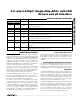
6kΩ
6kΩ
DOUT
DOUT
GND
GND
DV
DD
C
LOAD
50pF
C
LOAD
50pF
A) V
OH
TO HIGH-Z B) V
OL
TO HIGH-Z
Figure 13. Load Circuits for Disable Time
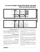
6kΩ
6kΩ
DOUT
DOUT
GND
GND
DV
DD
C
LOAD
50pF
C
LOAD
50pF
B) HIGH-Z TO V
OH
AND V
OL
TO V
OH
B) HIGH-Z TO V
OL
AND V
OH
TO V
OL
Figure 14. Load Circuits for Enable Time