
Datasheet


MAX1491/MAX1493/MAX1495
3.5- and 4.5-Digit, Single-Chip
ADCs with LCD Drivers
18 ______________________________________________________________________________________
offers enhanced offset calibration on demand. Connect
HOLD to DV
DD
for 2s to perform enhanced offset cali-
bration.
Peak
The MAX1491/MAX1493/MAX1495 feature peak detec-
tion circuitry. When activated (PEAK connected to DV
DD
),
the devices display only the highest voltage measured to
the LCD. First, the current ADC result is displayed. Then
the new ADC conversion result is compared to this value.
If the new value is larger than the previous peak value,
the new value is displayed. If the new value is less than
the previous peak value, the display remains unchanged.
Connect PEAK to GND to clear the peak value and dis-
able the peak function. The peak function is only valid for
the -19,487 to +19,999 range for the MAX1493/
MAX1495 and -1217 to +1999 for the MAX1491.
Hold
The MAX1491/MAX1493/MAX1495 feature data HOLD
circuitry. When activated (HOLD connected to DV
DD
),
the devices hold the current reading on the LCD.
Low Battery
The MAX1491/MAX1493/MAX1495 feature a low-battery
detection input. When the voltage at LOWBATT drops
below 2.048V (typ), the LOWBATT segment of the LCD
turns on.
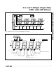
Strain Gauge Measurement
Connect the differential inputs of the MAX1491/
MAX1493/MAX1495 to the bridge network of the strain
gauge. In Figure 13, the analog supply voltage powers
the bridge network and the MAX1491/MAX1493/
MAX1495 along with its reference voltage. The
MAX1491/MAX1493/MAX1495 handle an analog input
voltage range of ±200mV or ±2V full scale. The ana-
log/reference inputs of the part allow the analog input
range to have an absolute value anywhere between
-2.2V and +2.2V.
4–20mA Measurement
To measure 4–20mA signals, connect a shunt resistor
across AIN+ and AIN- to create the ±2V or ±200mV
input voltage (see Figure 14).
Table 4. LCD Priority Table
HOLD PEAK DISPLAYS
DV
DD
X Current value
GND DV
DD
Peak value
GND GND Latest ADC result
Figure 13. Strain-Gauge Application with the MAX1491/MAX1493/
MAX1495
MAX1491
MAX1493
MAX1495
AV
DD
DV
DD
4.7µF
0.1µF
0.1µF
0.1µF
0.1µF
0.1µF
ANALOG SUPPLY
FERRITE
BEAD
R
REF
R
R
ACTIVE
GAUGE
DUMMY
GAUGE
REF+
V
NEG
REF-
AIN+
AIN-
GND
4.7µF
0.1µF
INTREF
0.1µF
Figure 14. 4–20mA Measurement
0.1µF
R
AIN-
AIN+
4–20mA
R = 100
Ω for ±2V RANGE
10
Ω for ±200mV RANGE
0.1µF
MAX1491
MAX1493
MAX1495
±1.8.8.8.8