
Datasheet


315MHz/433MHz ASK Superheterodyne
Receiver with Extended Dynamic Range
where f
C
is the desired 3dB corner frequency.
For example, choose a Butterworth filter response with
a corner frequency of 5kHz:
Choosing standard capacitor values changes C7 to
470pF and C6 to 220pF, as shown in the
Typical
Application Circuit
.
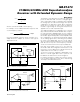
Data Slicer
The purpose of the data slicer is to take the analog out-
put of the data filter and convert it to a digital signal.
This is achieved by using a comparator and comparing
the analog input to a threshold voltage. One input is
supplied by the data filter output. Both comparator
inputs are accessible off chip to allow for different
methods of generating the slicing threshold, which is
applied to the second comparator input.
The suggested data slicer configuration uses a resistor
(R1) connected between DSN and DSP with a capaci-
tor (C8) from DSN to DGND (Figure 2). This configura-
tion averages the analog output of the filter and sets the
threshold to approximately 50% of that amplitude. With
this configuration, the threshold automatically adjusts
as the analog signal varies, minimizing the possibility
for errors in the digital data. The sizes of R1 and C8
affect how fast the threshold tracks to the analog ampli-
tude. Be sure to keep the corner frequency of the RC
circuit much lower than the lowest expected data rate.
Note that a long string of zeros or 1’s can cause the
threshold to drift. This configuration works best if a cod-
ing scheme, such as Manchester coding, which has an
equal number of zeros and 1’s, is used.
To prevent continuous toggling of DATAOUT in the
absence of an RF signal due to noise, hysteresis can
be added to the data slicer as shown in Figure 3.
For further information on Data Slicer options, please
refer to Maxim Application Note 3671,
Data Slicing
Techniques for UHF ASK Receivers
.
C
kkHz
pF7
1 000
1 414 100 3 14 5
450
.
..
=
()( )()()
≈
Ω
C
b
ak f
C
a
kf
c
c
7
100
6
4 100
=
()()
()
=
()()
()
π
π
RSSI
R
DF1
100kΩ
R
DF2
100kΩ
C7
19
DFO
21
OPP
22
DFFB
C6
MAX1473
Figure 1. Sallen-Key Lowpass Data Filter
DATA
SLICER
R1
25
DATAOUT
20
DSN
19
DFO
23
DSP
C8
MAX1473
Figure 2. Generating Data Slicer Threshold
DATA
SLICER
R3
R2
R*
R1
25
DATAOUT
*OPTIONAL
23
DSP
19
DFO
20
DSN
C8
MAX1473
Figure 3. Generating Data Slicer Hysteresis
MAX1473
Maxim Integrated
11