9-4252; Rev 1; 10/08 12-/16-Bit DASs with ADC, DACs, DPIOs, APIOs, Reference, Voltage Monitors, and Temp Sensor Applications Battery-Powered and Portable Devices Electrochemical and Optical Sensors Medical Instruments Industrial Control Data Acquisition Systems Low-Cost CODECs Features ♦ 1.8V to 3.6V Single Digital Supply Operation ♦ Internal Charge Pump for Analog Circuits (2.7V to 5.
MAX1329/MAX1330 12-/16-Bit DASs with ADC, DACs, DPIOs, APIOs, Reference, Voltage Monitors, and Temp Sensor ABSOLUTE MAXIMUM RATINGS AGND to DGND.................................................... -0.3V to +0.3V Continuous Current into Any Pin.......................................±50mA Continuous Power Dissipation (TA = +70°C) 40-Pin Thin QFN (derate 37mW/°C above +70°C) ....2963mW Operation Temperature Range............................-40°C to +85°C Storage Temperature Range .............................
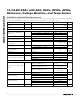
12-/16-Bit DASs with ADC, DACs, DPIOs, APIOs, Reference, Voltage Monitors, and Temp Sensor (DVDD = 1.8V to 3.6V, AVDD = 2.7V to 5.5V, VREFDAC = VREFADC = 2.5V, external reference; 10µF capacitor at REFADC and REFDAC; 0.01µF capacitor at REFADJ; TA = TMIN to TMAX, unless otherwise noted. Typical values are at TA = +25°C.) PARAMETER Aperture Jitter SYMBOL CONDITIONS MIN tAJ TYP Gain = 1, 2; DVDD ≥ 2.7V, AVDD ≥ 5.
MAX1329/MAX1330 12-/16-Bit DASs with ADC, DACs, DPIOs, APIOs, Reference, Voltage Monitors, and Temp Sensor ELECTRICAL CHARACTERISTICS (continued) (DVDD = 1.8V to 3.6V, AVDD = 2.7V to 5.5V, VREFDAC = VREFADC = 2.5V, external reference; 10µF capacitor at REFADC and REFDAC; 0.01µF capacitor at REFADJ; TA = TMIN to TMAX, unless otherwise noted. Typical values are at TA = +25°C.
12-/16-Bit DASs with ADC, DACs, DPIOs, APIOs, Reference, Voltage Monitors, and Temp Sensor (DVDD = 1.8V to 3.6V, AVDD = 2.7V to 5.5V, VREFDAC = VREFADC = 2.5V, external reference; 10µF capacitor at REFADC and REFDAC; 0.01µF capacitor at REFADJ; TA = TMIN to TMAX, unless otherwise noted. Typical values are at TA = +25°C.
MAX1329/MAX1330 12-/16-Bit DASs with ADC, DACs, DPIOs, APIOs, Reference, Voltage Monitors, and Temp Sensor ELECTRICAL CHARACTERISTICS (continued) (DVDD = 1.8V to 3.6V, AVDD = 2.7V to 5.5V, VREFDAC = VREFADC = 2.5V, external reference; 10µF capacitor at REFADC and REFDAC; 0.01µF capacitor at REFADJ; TA = TMIN to TMAX, unless otherwise noted. Typical values are at TA = +25°C.) PARAMETER SYMBOL CONDITIONS MIN TYP MAX UNITS Temperature Resolution VREFADC = 2.
12-/16-Bit DASs with ADC, DACs, DPIOs, APIOs, Reference, Voltage Monitors, and Temp Sensor (DVDD = 1.8V to 3.6V, AVDD = 2.7V to 5.5V, VREFDAC = VREFADC = 2.5V, external reference; 10µF capacitor at REFADC and REFDAC; 0.01µF capacitor at REFADJ; TA = TMIN to TMAX, unless otherwise noted. Typical values are at TA = +25°C.) PARAMETER SYMBOL Turn-On Time CONDITIONS MIN AVDD = 2.
MAX1329/MAX1330 12-/16-Bit DASs with ADC, DACs, DPIOs, APIOs, Reference, Voltage Monitors, and Temp Sensor ELECTRICAL CHARACTERISTICS (continued) (DVDD = 1.8V to 3.6V, AVDD = 2.7V to 5.5V, VREFDAC = VREFADC = 2.5V, external reference; 10µF capacitor at REFADC and REFDAC; 0.01µF capacitor at REFADJ; TA = TMIN to TMAX, unless otherwise noted. Typical values are at TA = +25°C.
12-/16-Bit DASs with ADC, DACs, DPIOs, APIOs, Reference, Voltage Monitors, and Temp Sensor (DVDD = 1.8V to 3.6V, AVDD = 2.7V to 5.5V, VREFDAC = VREFADC = 2.5V, external reference; 10µF capacitor at REFADC and REFDAC; 0.01µF capacitor at REFADJ; TA = TMIN to TMAX, unless otherwise noted. Typical values are at TA = +25°C.) PARAMETER SYMBOL CONDITIONS MIN TYP MAX 0.7 x DVDD Input High Voltage V DPIO1–DPIO4 0.3 x DVDD CLKIO 0.
MAX1329/MAX1330 12-/16-Bit DASs with ADC, DACs, DPIOs, APIOs, Reference, Voltage Monitors, and Temp Sensor TIMING CHARACTERISTICS (DVDD = 1.8V to 3.6V, AVDD = 2.7V to 5.5V, TA = TMIN to TMAX, unless otherwise noted.) PARAMETER SYMBOL CONDITIONS SERIAL-INTERFACE TIMING PARAMETERS (DVDD = 2.7V to 3.
12-/16-Bit DASs with ADC, DACs, DPIOs, APIOs, Reference, Voltage Monitors, and Temp Sensor (DVDD = 1.8V to 3.6V, AVDD = 2.7V to 5.5V, TA = TMIN to TMAX, unless otherwise noted.
Typical Operating Characteristics (AVDD = 5.0V, VREFADC = VREFDAC = 2.5V for DVDD = 3.0V; TA = +25°C, unless otherwise noted.) 1.75 TA = -40°C TA = +85°C 0.4 1.50 1.25 IDVDD (μA) IDVDD (mA) 1.75 1.50 TA = +25°C 0.6 2.00 TA = +85°C TA = +25°C 1.00 TA = -40°C 1.25 IDVDD (μA) 0.8 STATIC DIGITAL SUPPLY CURRENT vs. DIGITAL SUPPLY VOLTAGE (SHUTDOWN) MAX1329 toc03 2.00 MAX1329 toc01 1.0 STATIC DIGITAL SUPPLY CURRENT vs.
12-/16-Bit DASs with ADC, DACs, DPIOs, APIOs, Reference, Voltage Monitors, and Temp Sensor ADC INTEGRAL NONLINEARITY vs. DIGITAL INPUT CODE (AVDD = 3.0V) 0.4 0.4 0.2 0.2 0 -0.2 -0.6 -0.6 -0.8 -0.8 95 1024 2048 90 0 4096 3072 1024 2048 3072 2.5 4096 3.0 3.5 4.0 4.5 DIGITAL INPUT CODE DIGITAL INPUT CODE AVDD (V) ADC SUPPLY CURRENT vs. CONVERSION RATE ADC OFFSET VOLTAGE vs. TEMPERATURE ADC OFFSET ERROR vs. SUPPLY VOLTAGE A 250 200 F 150 AVDD = 2.7V 0.3 AVDD = 5.5V 0.2 5.
Typical Operating Characteristics (continued) (AVDD = 5.0V, VREFADC = VREFDAC = 2.5V for DVDD = 3.0V; TA = +25°C, unless otherwise noted.) ADC GAIN ERROR vs. TEMPERATURE ADC GAIN ERROR vs. SUPPLY VOLTAGE AV = 1 GAIN ERROR (%) AVDD = 5.5V 0.03 0.02 MAX1329 toc17 AV = 1 0.04 ERROR (%) 0.023 MAX1329 toc16 0.05 0.022 0.021 AVDD = 2.7V 0.01 0.020 0 -40 -15 10 35 60 2.7 85 3.7 ADC ENOB vs. FREQUENCY -40 -60 -80 -100 MAX1329 toc19 12.5 12.0 11.5 11.0 10.5 10.
12-/16-Bit DASs with ADC, DACs, DPIOs, APIOs, Reference, Voltage Monitors, and Temp Sensor ADC REFERENCE VOLTAGE (1.25V) vs. LOAD CURRENT B 2.054 2.052 C 1.2505 VREFADC (V) VREFADC (V) 1.2510 MAX1329 toc21 A 1.2515 2.056 MAX1329 toc20 1.2520 ADC REFERENCE VOLTAGE (2.048V) vs. LOAD CURRENT D 1.2500 1.2495 2.050 A 2.048 B D E E 2.044 1.2490 F 1.2485 1.2480 -100 0 F 2.
Typical Operating Characteristics (continued) (AVDD = 5.0V, VREFADC = VREFDAC = 2.5V for DVDD = 3.0V; TA = +25°C, unless otherwise noted.) MAX1329 toc26 MAX1329 toc25 2.510 MAX1329 toc24 2.055 2.054 2.053 2.052 2.051 2.050 2.049 2.048 2.047 2.046 2.045 2.044 2.043 2.042 2.041 ADC REFERENCE LINE TRANSIENT (VADCREF = +1.25V) ADC REFERENCE VOLTAGE (2.5V) vs. ANALOG SUPPLY VOLTAGE ADC REFERENCE VOLTAGE (2.048V) vs. ANALOG SUPPLY VOLTAGE 2.508 2.506 500mV/div 2.
12-/16-Bit DASs with ADC, DACs, DPIOs, APIOs, Reference, Voltage Monitors, and Temp Sensor ADC REFERENCE LINE TRANSIENT (VADCREF = +2.5V) ADC REFERENCE SUPPLY CURRENT vs. ANALOG SUPPLY VOLTAGE 5V 20mV/div VADCREF 444 IAVDD (µA) AV DD 2.5V 443 2.048V 2.5V 442 1.25V 440 4 4.0 4.5 5.0 5.5 3.0 3.5 4.0 4.5 5.0 5.5 AVDD SUPPLY VOLTAGE (V) DAC INTEGRAL NONLINEARITY vs. DIGITAL INPUT CODE (AVDD = 5V) DAC DIFFERENTIAL NONLINEARITY vs. DIGITAL INPUT CODE (AVDD = 3V) VREFDAC = 2.5V 2.0 0.
Typical Operating Characteristics (continued) (AVDD = 5.0V, VREFADC = VREFDAC = 2.5V for DVDD = 3.0V; TA = +25°C, unless otherwise noted.) DAC SLEW RATE/CROSSTALK TRANSIENT RESPONSE (VREFDAC = +2.048V) DAC SLEW RATE/CROSSTALK TRANSIENT RESPONSE (VREFDAC = +1.25V) DAC GAIN ERROR vs. TEMPERATURE MAX1329 toc42 MAX1329 toc41 MAX1329 toc40 -0.800 -0.825 -0.850 AVDD = +5.0V AVDD = +5.0V 2.048V 1.25V AVDD = 2.7V VOUTA 1V/div VOUTB 1mV/div VOUTB 1V/div VOUTA -0.875 -0.900 -0.
12-/16-Bit DASs with ADC, DACs, DPIOs, APIOs, Reference, Voltage Monitors, and Temp Sensor OP-AMP SUPPLY CURRENT vs. ANALOG SUPPLY VOLTAGE 70 60 PSRR (dB) 80 75 70 AVDD = 3.0V 50 40 65 60 450 400 350 300 250 200 150 100 30 50 55 0 20 3.0 3.5 4.0 4.5 5.0 5.5 0.01 0.1 AVDD (V) 1 10 FREQUENCY (kHz) 40 30 A B 20 D C 10 10 100 1000 OP-AMP MAXIMUM OUTPUT VOLTAGE vs.
Typical Operating Characteristics (continued) (AVDD = 5.0V, VREFADC = VREFDAC = 2.5V for DVDD = 3.0V; TA = +25°C, unless otherwise noted.) ANALOG SWITCH ON-RESISTANCE vs. COM VOLTAGE (AVDD = 3V) 0 -60 -120 -150 115 1 10 105 100 95 90 100 AVDD = 3V CL = 220pF TA = -40°C 80 0 1000 100 TA = -40°C 85 95 90 0.1 0.5 1.0 1.5 2.0 3.0 2.5 2 1 3 4 5 6 FREQUENCY (kHz) COM VOLTAGE (V) COM VOLTAGE (V) ANALOG SWITCH TURN-ON/-OFF TIME vs.
12-/16-Bit DASs with ADC, DACs, DPIOs, APIOs, Reference, Voltage Monitors, and Temp Sensor τ = 11s 80 INTERNAL 0 -0.5 110 60 40 90 20 85 -1.5 80 0 -15 10 35 85 60 -5 15 35 55 75 95 2.5 115 3.5 4.0 4.5 5.0 AVDD (V) CHARGE-PUMP EFFICIENCY vs. OUTPUT CURRENT (AVDD = 3V) CHARGE-PUMP EFFICIENCY vs. OUTPUT CURRENT (AVDD = 4V) CHARGE-PUMP EFFICIENCY vs. OUTPUT CURRENT (AVDD = 5V) DVDD = 2.0V 70 DVDD = 2.5V 60 DVDD = 2.5V 80 DVDD = 3.0V 50 DVDD = 2.2V 90 40 70 DVDD = 3.
Typical Operating Characteristics (continued) (AVDD = 5.0V, VREFADC = VREFDAC = 2.5V for DVDD = 3.0V; TA = +25°C, unless otherwise noted.) CHARGE-PUMP OUTPUT VOLTAGE vs. OUTPUT CURRENT (AVDD = 5V) 5.1 DVDD = 3.6V CHARGE-PUMP LOAD TRANSIENT RESPONSE FOR 0.1mA TO 1.0mA LOAD CHARGE-PUMP RIPPLE (IOUT = 5mA, DVDD = 2V, CHARGE-PUMP CLOCK = 78kHz) MAX1329 toc71 MAX1329 toc70 MAX1329 toc69 5.2 AVDD = +3.0V, DVDD = +2.0V AVDD = +3.0V, DVDD = +2.0V 5.0 AVDD (V) 2mV/div AVDD 4.9 DVDD = 3.3V 4.
12-/16-Bit DASs with ADC, DACs, DPIOs, APIOs, Reference, Voltage Monitors, and Temp Sensor PIN NAME FUNCTION MAX1329 MAX1330 1 1 DPIO1 Digital Programmable Input/Output 1 2 2 DPIO2 Digital Programmable Input/Output 2 3 3 DPIO3 Digital Programmable Input/Output 3 4 4 DPIO4 Digital Programmable Input/Output 4 5 5 DOUT Serial-Data Output. DOUT outputs serial data from the data register. DOUT changes on the falling edge of SCLK and is valid on the rising edge of SCLK.
MAX1329/MAX1330 12-/16-Bit DASs with ADC, DACs, DPIOs, APIOs, Reference, Voltage Monitors, and Temp Sensor Pin Description (continued) PIN NAME MAX1329 MAX1330 24 24 OUTA 25 25 FBA 24 FUNCTION DACA Force-Sense Output. Also internally connected to ADC mux. DACA Force-Sense Feedback Input. Also internally connected to ADC mux. DAC Internal Reference Buffer Output/DAC External Reference Input. In internal reference mode, REFDAC provides a 1.25V, 2.048V, or 2.5V internal reference buffer output.
12-/16-Bit DASs with ADC, DACs, DPIOs, APIOs, Reference, Voltage Monitors, and Temp Sensor MAX1329/MAX1330 CS tCSH tCH tCYC tCSH tCSS tCL SCLK tDS tDH DIN tDV tDO tTR DOUT Figure 1. Detailed Serial-Interface Timing Diagram Detailed Description The MAX1329/MAX1330 smart DASs are based on a 312ksps, 12-bit SAR ADC with a 1ksps, 16-bit DSP mode.
MAX1329/MAX1330 12-/16-Bit DASs with ADC, DACs, DPIOs, APIOs, Reference, Voltage Monitors, and Temp Sensor INTERNAL OSCILLATOR 4.9152MHz (OFF, ON) DPIO configured as SLP or SHDN inputs. In normal mode, each analog and digital block can be powered up or shut down individually through its respective control register.
12-/16-Bit DASs with ADC, DACs, DPIOs, APIOs, Reference, Voltage Monitors, and Temp Sensor Digital and Analog Programmable I/Os The MAX1329/MAX1330 provide four digital programmable I/Os (DPIO1–DPIO4) and four analog programmable I/Os (APIO1–APIO4). The DPIOs and APIOs can be configured as logic inputs or outputs through the DPIO and APIO Control registers. The DPIOs are powered by DVDD. Likewise, the APIOs are powered by AVDD.
MAX1329/MAX1330 12-/16-Bit DASs with ADC, DACs, DPIOs, APIOs, Reference, Voltage Monitors, and Temp Sensor Single-Pole/Double-Throw (SPDT) Switches The MAX1329/MAX1330 provide two uncommitted SPDT switches that can also be configured as a doublepole/single-throw (DPST) switch (see Tables 28 and 29). Each switch has a typical on-resistance of 115Ω at AVDD = 3V. The switch is controlled through the Switch Control register or a DPIO configured to control the switches.
12-/16-Bit DASs with ADC, DACs, DPIOs, APIOs, Reference, Voltage Monitors, and Temp Sensor 1111 1111 1101 0111 1111 1101 0000 0000 0011 1 LSB = 0000 0000 0001 0000 0000 0000 1111 1111 1111 0000 0000 0010 1000 0000 0010 0000 0000 0001 1000 0000 0001 0000 0000 0000 0 1 2 4093 3 4095 INPUT VOLTAGE (LSB) VREFADC (GAIN x 4096) VREFADC (2 x GAIN) VREFADC (GAIN x 4096) VREFADC/GAIN BINARY OUTPUT CODE 1 LSB = TWO'S COMPLEMENT OUTPUT CODE 0111 1111 1110 VREFADC (2 x GAIN) 0111 1111 1111 FULL
MAX1329/MAX1330 12-/16-Bit DASs with ADC, DACs, DPIOs, APIOs, Reference, Voltage Monitors, and Temp Sensor FROM REFDAC FROM SERIAL I/O DAC INPUT REGISTER FIFOA CONTROL REGISTER DAC OUTPUT REGISTER TO DAC OUTPUT BUFFER 12-BIT DAC 16-WORD DAC FIFO DDS LOGIC FOR DACA ONLY Figure 7. Detailed DAC and FIFO Block Diagram determines the analog output voltage. An internal switch configures the force-sense output for unity gain configuration when it is closed.
12-/16-Bit DASs with ADC, DACs, DPIOs, APIOs, Reference, Voltage Monitors, and Temp Sensor 16 12 12 12 FIFO LOCATION 16 FIFO LOCATION 8 0 0 0 0 16 32 48 64 80 96 0 112 128 16 32 48 64 80 96 (d) OUTPUT WAVEFORM (UNIPOLAR, SYMMETRIC, CONTINUOUS) (e) OUTPUT WAVEFORM (UNIPOLAR, ASYMMETRIC, SINGLE) FIFO LOCATION 8 4 0 16 32 48 64 80 96 16 16 12 12 8 8 4 0 -4 -12 32 48 64 80 16 16 12 12 8 8 4 0 -4 -16 112 128 0 16 32 -12 48 64 80 96 112 128 SEQUENCE
MAX1329/MAX1330 12-/16-Bit DASs with ADC, DACs, DPIOs, APIOs, Reference, Voltage Monitors, and Temp Sensor Table 2. Direct-Mode Definitions COMMAND NAME START CONTROL ADC Convert 1 DACA Write 0 1 R/W 0 MUX<3:0> DACB Write 0 1 R/W 1 Register Mode* 0 0 R/W GAIN<1:0> BIP DACA<11:0> DACB<11:0> ADDRESS (ADR<4:0>) DATA (D<255:0>, D<23:0>, D<15:0>, or D<7:0>) *See Table 3. Asserting the BIPA bit with SYMA = 1 creates phases three and four (see Figure 9g).
12-/16-Bit DASs with ADC, DACs, DPIOs, APIOs, Reference, Voltage Monitors, and Temp Sensor MAX1329/MAX1330 CS SCLK X DIN 0 0 0 A4 A3 A2 A1 A0 DN-1 DN -2 DN-3 DN-4 D2 D1 D0 X X X X X X X X DN-1 DN-2 DN-3 DN-4 D2 D1 D0 DOUT X = DON’T CARE. Figure 10. Variable Length Register-Mode Data-Write Operation CS SCLK DIN X 0 0 1 A4 A3 A2 A1 A0 DOUT X X = DON’T CARE. Figure 11.
MAX1329/MAX1330 12-/16-Bit DASs with ADC, DACs, DPIOs, APIOs, Reference, Voltage Monitors, and Temp Sensor CS SCLK DIN 0 X 1 0 AB D 11 D 10 D9 D8 D7 D6 D5 D3 D4 D2 D1 X D0 DOUT X = DON'T CARE. Figure 13. Write to DACA (AB = 0) or DACB (AB = 1). The DAC Control register programs the write mode. CS SCLK DIN 0 X 1 1 AB DOUT X X X X X X X X X X X X D 11 D 10 D9 D8 D7 D6 D5 D4 D3 D2 D1 D0 X X = DON'T CARE. Figure 14.
12-/16-Bit DASs with ADC, DACs, DPIOs, APIOs, Reference, Voltage Monitors, and Temp Sensor MAX1329/MAX1330 CS SCLK DIN X 0 1 0 AB D 11 D9 D 10 D8 D7 DAC D6 D5 D4 D3 D2 D1 D0 X X X X PREVIOUS OUTPUT DPIO X X X X NEW OUTPUT RISING EDGE TRIGGERED X = DON'T CARE. Figure 16.
MAX1329/MAX1330 12-/16-Bit DASs with ADC, DACs, DPIOs, APIOs, Reference, Voltage Monitors, and Temp Sensor CS SCLK DIN 1 X 1 2 3 4 5 6 7 8 9 10 11 12 13 14 15 16 17 18 19 20 21 22 23 24 25 M3 M2 M1 M0 G1 G0 BIP X X X X X X X X X X X X X X X X X D9 D8 D7 D6 D5 D4 D3 D2 D1 D0 D 11 D10 DOUT TRACK ADC MODE CONVERT TRACK D 11 CONVERT ADCDONE* *ADCDONE IS AN INTERNAL SIGNAL. RISING EDGE OF ADCDONE SETS THE ADD BIT IN THE STATUS REGISTER.
12-/16-Bit DASs with ADC, DACs, DPIOs, APIOs, Reference, Voltage Monitors, and Temp Sensor When writing to the ADC Control register in fast powerdown mode with autoconvert disabled, acquisition begins on the 1st rising ADC clock edge after CS transitions high, and ends after the programmed number of clock cycles. The conversion completes a minimum 14 clock cycles after acquisition ends.
MAX1329/MAX1330 12-/16-Bit DASs with ADC, DACs, DPIOs, APIOs, Reference, Voltage Monitors, and Temp Sensor CS THERE ARE TWO ADC CONVERSIONS PER TEMPERATURE CONVERSION. TEMP CONVERT COMMAND (SCLK, DIN, DOUT NOT SHOWN) WAIT PERIOD 93.5 CLOCKS ADC MODE 1ST AQUISITION 90 CLOCKS 1ST CONVERSION 19 CLOCKS 2ND AQUISITION 87 CLOCKS 2ND CONVERSION 17.5 CLOCKS TRACK CONVERT TRACK CONVERT 1 CLOCK = 1/(ADC MASTER CLOCK FREQUENCY) START STOP Figure 22.
12-/16-Bit DASs with ADC, DACs, DPIOs, APIOs, Reference, Voltage Monitors, and Temp Sensor Table 3.
MAX1329/MAX1330 12-/16-Bit DASs with ADC, DACs, DPIOs, APIOs, Reference, Voltage Monitors, and Temp Sensor Table 3.
12-/16-Bit DASs with ADC, DACs, DPIOs, APIOs, Reference, Voltage Monitors, and Temp Sensor MAX1329/MAX1330 Table 4. ADC Autoconvert Bit Configuration (AUTO<2:0>) AUT02 AUTO1 AUTO0 ADC MASTER CLOCK CYCLES 0 0 0 Autoconvert disabled 0 0 1 32 0 1 0 64 0 1 1 128 1 0 0 256 1 0 1 512 1 1 0 1024 1 1 1 2048 Table 5.
MAX1329/MAX1330 12-/16-Bit DASs with ADC, DACs, DPIOs, APIOs, Reference, Voltage Monitors, and Temp Sensor ADC Setup Register The ADC Setup register configures the input multiplexer, ADC gain, and unipolar/bipolar modes to perform a data conversion. Changes made to the ADC Setup register settings are applied immediately. If changes are made during a conversion in progress, discard the results of that conversion to ensure a valid conversion result. MSEL: Multiplexer Select bit (default = 0).
12-/16-Bit DASs with ADC, DACs, DPIOs, APIOs, Reference, Voltage Monitors, and Temp Sensor MAX1329/MAX1330 Table 8.
MAX1329/MAX1330 12-/16-Bit DASs with ADC, DACs, DPIOs, APIOs, Reference, Voltage Monitors, and Temp Sensor ADC Data Register The ADC Data register contains the result from the most recently completed analog-to-digital conversion. The 12-bit result is stored in the ADCDATA<11:0> bits. The data format is binary for unipolar mode and two’s complement for bipolar mode.
12-/16-Bit DASs with ADC, DACs, DPIOs, APIOs, Reference, Voltage Monitors, and Temp Sensor A single read from the ADC FIFO register returns the ADC FIFO data and the 4-bit FIFO address (AFFA<3:0>) corresponding to the location read. After clocking out the 16-bit word, the read pointer increments and continual clock shifts out the 16-bit word at the location pointed to by the ADC FIFO read pointer.
MAX1329/MAX1330 12-/16-Bit DASs with ADC, DACs, DPIOs, APIOs, Reference, Voltage Monitors, and Temp Sensor ADC Accumulator Register The ADC Accumulator register contains the bits to enable dither, set the accumulator count, and set the 20-bit accumulator data. The dither and accumulator count bits are read/write and the accumulator data is read only. A write to the register resets the accumulator data (ACCDATA<19:0>) to 0x00000 and starts new accumulation.
12-/16-Bit DASs with ADC, DACs, DPIOs, APIOs, Reference, Voltage Monitors, and Temp Sensor results needed to be greater than the alarm threshold before the GTA Status bit is set (see Table 13). GTAT<11:0>: ADC Greater-Than Alarm Threshold bits (default = 0xFFF). When the required number of conversion results greater than the threshold set by the GTAT<11:0> bits have been completed, the GTA Status bit is set in the Status register.
MAX1329/MAX1330 12-/16-Bit DASs with ADC, DACs, DPIOs, APIOs, Reference, Voltage Monitors, and Temp Sensor ADC LT Alarm Register The ADC LT Alarm register contains the less-than mode, trip count, and threshold settings. Writing the register address resets the trip counters to zero. The LT alarm is functional for the normal, fast power-down, and burst modes. LTAM: ADC Less-Than Alarm Mode bit (default = 0). LTAM = 0 means that the alarm trips need not be consecutive to cause the LTA Status bit to be set.
12-/16-Bit DASs with ADC, DACs, DPIOs, APIOs, Reference, Voltage Monitors, and Temp Sensor OA1E: Op Amp 1 Enable bit (default = 0). Set OA1E = 1 to power up op amp 1. OA2E (MAX1330 only): Op Amp 2 Enable bit (default = 0). Set OA2E = 1 to power up op amp 2. DREF<1:0>: DAC Reference Buffer bits (default = 00). DREF<1:0> sets the DAC reference buffer gain when REFE = 0 (see Table 16). DREF<1:0> sets the REFDAC voltage when the REFE = 1. REFE: Internal Reference Enable bit (default = 0).
MAX1329/MAX1330 12-/16-Bit DASs with ADC, DACs, DPIOs, APIOs, Reference, Voltage Monitors, and Temp Sensor FIFOA Control Register The FIFOA Control register enables the DACA FIFO, configures the bipolar, symmetry, and continuous modes, and sets the depth of the FIFO. Any change to the contents of this register resets the FIFOA sequence to the starting location. If the FIFO operation is enabled (FFAE = 1), the next sequence command transfers the DACA input register data to the output register.
12-/16-Bit DASs with ADC, DACs, DPIOs, APIOs, Reference, Voltage Monitors, and Temp Sensor A write to the FIFOA Data register is possible only when the FFAE bit in the FIFOA Control register is 0. If FFAE = 1, any write to the FIFOA Data register is ignored. A read command is possible at any time. If BIPA = 0, the data is interpreted as binary (0 to 4095). If BIPA = 1, the data is interpreted as sign magnitude (-2047 to +2047).
MAX1329/MAX1330 12-/16-Bit DASs with ADC, DACs, DPIOs, APIOs, Reference, Voltage Monitors, and Temp Sensor FIFO Sequence Register A write to the FIFO Sequence register steps DACA to the next FIFOA word. A valid write consists of the 8-bit address and 8 bits of data, where the data bits are don’tcare bits. The FIFO location increments on the 16th rising edge of SCLK. Successive writes sequence the entire contents of the FIFOA Data register to the DACA output register.
12-/16-Bit DASs with ADC, DACs, DPIOs, APIOs, Reference, Voltage Monitors, and Temp Sensor VM2CP<2:0>: Voltage Monitor 2 (VM2) and ChargePump Control bits (default = 000). VM2CP<2:0> control the charge pump, the bypass switch, and the AVDD voltage monitor. The charge pump generates a regulated AVDD supply voltage from a DVDD input. When activated (VM2CP = 100), the bypass switch internally shorts DVDD to AVDD. VM2 monitors the voltage on AVDD and sets the VM2 Status bit when AV DD drops below the threshold.
MAX1329/MAX1330 12-/16-Bit DASs with ADC, DACs, DPIOs, APIOs, Reference, Voltage Monitors, and Temp Sensor Table 22. Voltage Monitor 2 and Charge-Pump Control Bit Configuration VM2CP2 VM2CP1 VM2CP0 CHARGE-PUMP STATE BYPASS SWITCH STATE VM2 STATE (THRESHOLD VOLTAGE) 0 0 0 Off Open Off 0 0 1 On (3V) Open On (2.7V) 0 1 0 On (4V) Open On (3.8V) 0 1 1 On (5V) Open On (4.5V) 1 0 0 Off Closed Off 1 0 1 Off Open On (2.7V) 1 1 0 Off Open On (3.
12-/16-Bit DASs with ADC, DACs, DPIOs, APIOs, Reference, Voltage Monitors, and Temp Sensor OSW1: Op Amp 1 Switch Control bit (default = 0). The OSW1 bit and DPIO_ configured in OSW1 mode control the state of the op amp 1 switch. If DPIO_ is not configured for OSW1 mode, it is set to 0 as shown in Table 26. OSW2 (MAX1330 only): Op Amp 2 Switch Control bit (default = 0). The OSW2 bit and DPIO_ configured in OSW2 mode control the state of the op amp 2 switch.
MAX1329/MAX1330 12-/16-Bit DASs with ADC, DACs, DPIOs, APIOs, Reference, Voltage Monitors, and Temp Sensor Table 26. Op Amp 1 Switch Control Configuration OSW1 BIT Table 27.
12-/16-Bit DASs with ADC, DACs, DPIOs, APIOs, Reference, Voltage Monitors, and Temp Sensor SPDT2 SWITCH STATE SPDT21 BIT SPDT20 BIT DPIO4 DPIO3 DPIO2 DPIO1 0 0 0 0 0 0 Open Open 0 X X X X 1 Closed Closed 0 X X X 1 X Closed Closed 0 X X 1 X X Closed Closed 0 X 1 X X X Closed Closed 0 1 X X X X Closed Closed 1 0 0 0 0 0 Open Closed 1 X X X X 1 Closed Open 1 X X X 1 X Closed Open 1 X X 1 X X Closed Open 1 X 1 X X X Clo
MAX1329/MAX1330 12-/16-Bit DASs with ADC, DACs, DPIOs, APIOs, Reference, Voltage Monitors, and Temp Sensor APIO Setup Register The APIO Setup register programs the resistor pullup and the logic level for APIO1–APIO4. AP<4:1>PU: APIO Resistor Pullup bits (default = 1111). AP_PU controls the internal 500kΩ (typ) pullup resistor on the corresponding APIO_. AP_PU = 0 disables the pullup resistor and AP_PU = 1 connects the pullup resistor to AVDD.
12-/16-Bit DASs with ADC, DACs, DPIOs, APIOs, Reference, Voltage Monitors, and Temp Sensor DP_MD3 DP_MD2 DP_MD1 DP_MD0 0 0 0 0 MODE DESCRIPTION MAX1329 MAX1330 GPI GPI Digital input. DPIO_ logic-level read from DP_LL register bit. 0 0 0 1 WUL WUL Digital input. A falling edge on WUL sets the OSCE bit enabling the oscillator. 0 0 1 0 WUH WUH Digital input. A rising edge on WUH sets the OSCE bit enabling the oscillator. Digital input.
MAX1329/MAX1330 12-/16-Bit DASs with ADC, DACs, DPIOs, APIOs, Reference, Voltage Monitors, and Temp Sensor Table 31. DPIO_ Mode Bit Configuration (continued) DP_MD3 DP_MD2 DP_MD1 DP_MD0 1 1 0 1 MODE MAX1330 SPDT2 SPDT2 Digital input. SPDT2 controls the SPDT2 switch. See the Switch Control Register section. 1 1 1 0 DRDY DRDY Digital output. DRDY goes high when a conversion is complete and valid ADC data is available in the ADC Data register.
12-/16-Bit DASs with ADC, DACs, DPIOs, APIOs, Reference, Voltage Monitors, and Temp Sensor MSB VM1A 0* VM1B 0* VM2 0 ADD 0 AFF 0 ACF 0 GTA 0 LTA 0 NAME DEFAULT APR4 0 APR3 0 APR2 0 APR1 0 APF4 0 APF3 0 APF2 0 APF1 0 NAME DEFAULT DPR4 0 DPR3 0 DPR2 0 DPR1 0 DPF4 0 DPF3 0 DPF2 0 LSB DPF1 0 *The default states for VM1A and VM1B are 0. However, at power-up, the voltage monitor asserts VM1A and VM1B. GTA: ADC Greater-Than (GT) Alarm Status bit (default = 0).
MAX1329/MAX1330 12-/16-Bit DASs with ADC, DACs, DPIOs, APIOs, Reference, Voltage Monitors, and Temp Sensor Interrupt Mask Register The Interrupt Mask register bits enable the Status bits to generate an interrupt on RST1 and/or RST2 if programmed as interrupts (configured by VM1<1:0> in the CP/VM Control register). Clearing a mask bit to 0 enables the corresponding bit in the Status register to generate an interrupt. Setting a mask bit to 1 prevents the Status bit from generating an interrupt.
12-/16-Bit DASs with ADC, DACs, DPIOs, APIOs, Reference, Voltage Monitors, and Temp Sensor 0.1µF 0.1µF DVDD C1A C1B AVDD MAX1329 MAX1330 DGND 2.7V TO 3.6V POWER SUPPLY AGND RST1 0.1µF 5.0V CDVDD VDD C1A DVDD C1B RESET DGND Figure 23. Power-Supply Circuit Using an External 3.0V Power Supply for DVDD and AVDD DGND RST2 DGND AGND Figure 24. Power-Supply Circuit Using an External 3.0V Power Supply for DVDD and Internal Charge Pump Set to 5V for AVDD Applications Information 1.
MAX1329/MAX1330 12-/16-Bit DASs with ADC, DACs, DPIOs, APIOs, Reference, Voltage Monitors, and Temp Sensor Communication with a Peripheral Device Powered by the MAX1329/MAX1330 XIN The circuit in Figure 27 shows the MAX1329/MAX1330 providing an interface between a µC and a peripheral device powered by different supply voltages. This eliminates the need for external level-translation circuitry due to the different supply voltages.
12-/16-Bit DASs with ADC, DACs, DPIOs, APIOs, Reference, Voltage Monitors, and Temp Sensor MAX1329/MAX1330 REFDAC OUTA DACA DSWA VBAT FBA LED SNO1 SCM1 SPDT1 Q1 SNC1 VBAT MAX1329 LED SNC2 SCM2 SPDT2 Q2 SNO2 REFDAC RB OUTB DACB DSWB IF RF FBB PHOTO DIODE AV = 0.5, 0.82, 1 2.5V REFADC 1.25V 1μF REFADJ REF REFDAC 2.50V AV = 0.5, 0.82, 1 0.01μF 1μF Figure 28.
MAX1329/MAX1330 12-/16-Bit DASs with ADC, DACs, DPIOs, APIOs, Reference, Voltage Monitors, and Temp Sensor the two LEDs. The LEDs can be powered directly from VBAT or from AVDD powered by the internal charge pump if the VD of the LEDs require a higher or regulated voltage. Ambient light rejection is performed in the digital domain in this configuration by digitizing the photodiode current with the internal ADC while both LEDs are off and subtracting this from the result when the LEDs are turned on.
12-/16-Bit DASs with ADC, DACs, DPIOs, APIOs, Reference, Voltage Monitors, and Temp Sensor MAX1329/MAX1330 MAX1329 REFDAC OUTA DACA IA DSWA RA FBA REFDAC OUTB DACB DSWB IB RB WE RE FBB SNO1 CE SCM1 SPDT1 SNC1 IN1OSW1 R1 OA1 OUT1 IN1+ 1.25V AV = 0.5, 0.82, 1 1μF REFADC REFADJ 2.5V REF REFDAC 2.50V AV = 0.5, 0.82, 1 0.01μF 1μF Figure 29.
MAX1329/MAX1330 12-/16-Bit DASs with ADC, DACs, DPIOs, APIOs, Reference, Voltage Monitors, and Temp Sensor MAX1330 IN1OSW1 RF OA1 OUT1 IN1+ 1.25V AV = 0.5, 0.82, 1 REFADC 2.5V REF WE 1μF REFADJ CE REFDAC 0.1μF 2.50V SENSOR AV = 0.5, 0.82, 1 1μF IN2R3 OSW2 OA2 OUT2 C1 R2 IN2+ C2 REFDAC OUTA R1 DACA DSWA FBA Figure 30.
12-/16-Bit DASs with ADC, DACs, DPIOs, APIOs, Reference, Voltage Monitors, and Temp Sensor MAX1329/MAX1330 AIN1 AIN1 AIN2 OUTA/OUT3 FBA/IN3- CAIN1* OUT1 IN1- AGND 2N3904 12-BIT ADC PGA MUX AV = 1, 2, 4, 8 OUTB/OUT2 FBB/IN2TEMP1 AIN2 TEMP2 TEMP3 DVDD/4 AVDD/4 CAIN2* AGND REFADC DITHER ACCUMULATOR ALARM ADC FIFO MUX REFADC 2N3904 REFDAC AGND AV = 0.5, 0.82, 1 MAX1329 MAX1330 TEMP SENSOR TEMP1 REFADC 1μF REFADJ 2.5V REF REFDAC AV = 0.5, 0.82, 1 0.
MAX1329/MAX1330 12-/16-Bit DASs with ADC, DACs, DPIOs, APIOs, Reference, Voltage Monitors, and Temp Sensor VIN+ IN1+ OUT1 OA1 VOUT IN1R3 OSW1 SNO1 SCM1 R2 SNC1 SPDT1 VIN- R1 IN2+ OUT2 OA2 IN2- R1 OSW2 SNO2 SCM2 R2 SNC2 SPDT2 MAX1330 R3 Figure 32. Programmable-Gain Instrumentation Amplifier, Switch Position 1 Round the FIFOA_DATA(n) values to the nearest integer and write these values to the FIFOA Data register. Figure 33 shows a sine wave with a 2VP-P output and with a 1.25V offset.
12-/16-Bit DASs with ADC, DACs, DPIOs, APIOs, Reference, Voltage Monitors, and Temp Sensor Operating the Analog Switches The MAX1329/MAX1330 include two single-pole doublethrow (SPDT) and three single-pole single-throw (SPST) analog switches. The two SPDT analog switches are uncommitted and the three SPST analog switches are connected between the DAC buffer or op amp outputs and the inverting inputs. The analog switches can be controlled using the Switch Control register or any of the DPIOs.
Using the Internal Reference and Reference Buffers The MAX1329/MAX1330 include a precision 2.5V internal reference and two independent programmable buffers for the ADC and DACs. See the ADC Control and DAC Control registers to enable the internal reference and program the buffers. The REFADJ output is fixed at 2.5V (REFE = 1) and the REFADC and REFDAC connect to the internal ADC reference input and the internal DAC reference inputs, respectively. These buffers can be programmed to output 1.25V, 2.
12-/16-Bit DASs with ADC, DACs, DPIOs, APIOs, Reference, Voltage Monitors, and Temp Sensor The ADC LT and GT alarms compare the latest ADC result to the values programmed in the ADC LT Alarm and ADC GT Alarm registers, if enabled, and assert the appropriate GTA or LTA status bit in the Status register once the threshold has been exceeded. The digital alarms can be used as a safeguard during normal ADC conversions to signify an event.
12-/16-Bit DASs with ADC, DACs, DPIOs, APIOs, Reference, Voltage Monitors, and Temp Sensor MAX1329/MAX1330 Functional Diagrams CLKIO DVDD CS SCLK INTERNAL CLOCK AND DIVIDER SERIAL I/O RST2 RST1 VOLTAGE SUPERVISORS AND INTERRUPTS AVDD C1B C1A DPIO1 CHARGE PUMP DPIO2 DPIO DPIO3 DIN DPIO4 AIN1 AIN2 OUTA DOUT AIN1 FBA OUT1 IN1OUTB AIN2 PGA UPPER MUX REFADC 12-BIT ADC AV = 1, 2, 4, 8 APIO1 DITHER FBB APIO2 APIO ACCUMULATOR APIO3 TEMP SENSOR ALARM TEMP1 TEMP2 TEMP3 DVDD/4 AVDD/4 L
12-/16-Bit DASs with ADC, DACs, DPIOs, APIOs, Reference, Voltage Monitors, and Temp Sensor CLKIO DVDD CS SCLK INTERNAL CLOCK AND DIVIDER SERIAL I/O RST2 RST1 C1B C1A VOLTAGE SUPERVISORS AND INTERRUPTS AVDD DPIO1 CHARGE PUMP DPIO2 DPIO DPIO3 DIN DPIO4 AIN1 AIN2 OUTA DOUT AIN1 FBA OUT1 IN1OUT2 AIN2 PGA UPPER MUX REFADC 12-BIT ADC AV = 1, 2, 4, 8 APIO1 DITHER IN2- APIO2 APIO ACCUMULATOR APIO3 TEMP SENSOR ALARM TEMP1 TEMP2 TEMP3 DVDD/4 AVDD/4 LOWER MUX AV = 0.5, 0.8192, 1.
12-/16-Bit DASs with ADC, DACs, DPIOs, APIOs, Reference, Voltage Monitors, and Temp Sensor MAX1329/MAX1330 Typical Operating Circuit 1.8V TO 3.6V 3.0V 10µF E1 0.1µF DVDD C1A 0.1µF 33µF 1µF C1B AVDD VDD XIN AIN1 32.768kHz MAX1329 AIN2 CLKIO XOUT HCLKIN REFADJ CS OUTPUT REFDAC SCLK SCK DIN MOSI DOUT MISO RST1 RESET RST2 INTERRUPT DPIO1 INTERRUPT DPIO2 INTERRUPT 2N3904 1µF REFADC 0.
12-/16-Bit DASs with ADC, DACs, DPIOs, APIOs, Reference, Voltage Monitors, and Temp Sensor 31 32 33 34 20 19 18 17 35 36 37 MAX1330 16 15 14 13 12 APIO4 APIO3 APIO2 AVDD C1B C1A DVDD DGND 38 39 EXPOSED PAD— CONNECT TO AGND 13 12 APIO4 APIO3 APIO2 11 APIO1 CLKIO 40 11 APIO1 31 32 33 34 20 19 18 17 AVDD C1B C1A 35 36 37 16 15 14 DVDD DGND 38 39 CLKIO 40 EXPOSED PAD— CONNECT TO AGND IN2+ REFADC REFADJ AGND REFADC REFADJ AGND MAX1329 IN2- AIN2 SNO2 SCM2 SNC2 FBB AIN2 SNO2 SCM
MAX1329/MAX1330 12-/16-Bit DASs with ADC, DACs, DPIOs, APIOs, Reference, Voltage Monitors, and Temp Sensor Revision History REVISION NUMBER REVISION DATE 0 8/08 Initial release — 1 10/08 Corrected Absolute Maximum Ratings table 2 DESCRIPTION PAGES CHANGED Maxim cannot assume responsibility for use of any circuitry other than circuitry entirely embodied in a Maxim product. No circuit patent licenses are implied.