
Datasheet


MAX1248/MAX1249
+2.7V to +5.25V, Low-Power, 4-Channel,
Serial 10-Bit ADCs in QSOP-16
14 ______________________________________________________________________________________
Float SHDN to select external compensation. The
Typical Operating Circuit
uses a 4.7µF capacitor at
VREF. A value of 4.7µF or greater ensures reference-
buffer stability and allows converter operation at the
2MHz full clock speed. External compensation increas-
es power-up time (see
Choosing Power-Down Mode
and Table 4).
Pull SHDN high to select internal compensation.
Internal compensation requires no external capacitor at
VREF and allows for the shortest power-up times. The
maximum clock rate is 2MHz in internal clock mode
and 400kHz in external clock mode.
Choosing Power-Down Mode
You can save power by placing the converter in a low-
current shutdown state between conversions. Select full
power-down or fast power-down mode via bits 1 and 0
of the DIN control byte with SHDN high or floating
(Tables 1 and 5). In both software power-down modes,
the serial interface remains operational, but the ADC
does not convert. Pull SHDN low at any time to shut
down the converter completely. SHDN overrides bits 1
and 0 of the control byte.
Full power-down mode turns off all chip functions that
draw quiescent current, reducing supply current typically
to 2µA. Fast power-down mode turns off all circuitry
except the bandgap reference. With fast power-down
mode, the supply current is 30µA. Power-up time can be
shortened to 5µs in internal compensation mode.
Table 4 shows how the choice of reference-buffer com-
pensation and power-down mode affects both power-up
delay and maximum sample rate. In external compensa-
tion mode, power-up time is 20ms with a 4.7µF compen-
sation capacitor when the capacitor is initially fully
discharged. From fast power-down, start-up time can be
eliminated by using low-leakage capacitors that do not
discharge more than 1/2LSB while shut down. In power-
down, leakage currents at VREF cause droop on the ref-
erence bypass capacitor. Figures 11a and 11b show
the various power-down sequences in both external and
internal clock modes.
SCLK
DIN
DOUT
CS
S CONTROL BYTE 0
CONTROL BYTE 1S
CONVERSION RESULT 0
B9 B8 B7 B6 B5 B4 B3 B2 B1 B0 S1 S0
CONVERSION RESULT 1
SSTRB
B9 B8 B7 B6 B5 B4 B3 B2 B1 B0 S1 S0
CONTROL BYTE 2S
1
8 1 8 1
CS
SCLK
DIN
DOUT
S CONTROL BYTE 0
CONTROL BYTE 1S
CONVERSION RESULT 0
B9 B8 B7 B6 B5 B4 B3 B2 B1 B0 S1 S0 B9 B8 B7 B6
CONVERSION RESULT 1
• • •
• • •
• • •
• • •
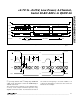
Figure 10a. External Clock Mode, 15 Clocks/Conversion Timing
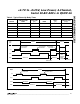
Figure 10b. External Clock Mode, 16 Clocks/Conversion Timing