
Datasheet


MAX1227/MAX1229/MAX1231
12-Bit 300ksps ADCs with FIFO,
Temp Sensor, Internal Reference
18 ______________________________________________________________________________________
Internally Timed Acquisitions and
Conversions Using the Serial Interface
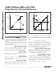
Performing Conversions in Clock Mode 10
In clock mode 10, the wake-up, acquisition, conversion,
and shutdown sequences are initiated by writing an
input data byte to the conversion register, and are per-
formed automatically using the internal oscillator. This is
the default clock mode upon power-up. See Figure 6
for clock mode 10 timing.
Initiate a scan by writing a byte to the conversion regis-
ter. The MAX1227/MAX1229/MAX1231 then power up,
scan all requested channels, store the results in the
FIFO, and shut down. After the scan is complete, EOC
is pulled low and the results are available in the FIFO. If
a temperature measurement is requested, the tempera-
ture result precedes all other FIFO results. EOC stays
low until CS is pulled low again.
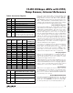
CS
DOUT
SCLK
CNVST
EOC
(CONVERSION2)
MSB1
LSB1
MSB2
(ACQUISITION1)
(ACQUISITION2)
(CONVERSION1)
REQUEST MULTIPLE CONVERSIONS BY SETTING CNVST LOW FOR EACH CONVERSION.
Figure 5. Clock Mode 01
(UP TO 514 INTERNALLY CLOCKED ACQUISITIONS AND CONVERSIONS)
MSB1
LSB1
MSB2
(CONVERSION BYTE)
CS
DOUT
SCLK
DIN
EOC
THE CONVERSION BYTE BEGINS THE ACQUISITION. CNVST IS NOT REQUIRED.
Figure 6. Clock Mode 10