
Datasheet


20 Maxim Integrated
2Msps/3Msps, Low-Power,
Serial 12-/10-/8-Bit ADCs
MAX11102/03/05/06/10/11/15/16/17
Pin Description
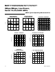
Pin Configurations
1
3
4
10
8
7
SCLK
OVDD
CHSEL
*CONNECT EXPOSED PAD TO GROUND PLANE. DEVICES DO NOT OPERATE WHEN EP IS NOT CONNECTED TO GROUND!
AGND
REF
MAX11102
MAX11103
MAX11106
MAX11111
29
DOUTAIN2
AIN1
56
CSV
DD
TDFN
TOP VIEW
EP*
EP*
+
TOP VIEW
+
TOP VIEW
GND
SCLKAIN
16
CS
5 DOUT
V
DD
MAX11105
MAX11110
MAX11115
MAX11116
MAX11117
SOT23
2
34
+
µMAX
29DOUTAIN2
110 SCLKAIN1
OVDDAGND 38
CHSELREF 7
CSV
DD
6
MAX11102
MAX11103
4
5
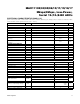
PIN
NAME FUNCTION
TDFN µMAX SOT23
1 1 — AIN1
Analog Input Channel 1. Single-ended analog input with respect to AGND with range
of 0V to V
REF
.
2 2 — AIN2
Analog Input Channel 2. Single-ended analog input with respect to AGND with range
of 0V to V
REF.
— — 3 AIN
Analog Input Channel. Single-ended analog input with respect to GND with range of
0V to V
DD.
— — 2 GND Ground. Connect GND to the GND ground plane.
3 3 — AGND Analog Ground. Connect AGND directly the GND ground plane.
4 4 — REF
External Reference Input. REF defines the signal range of the input signal AIN1/AIN2:
0V to V
REF
. The range of V
REF
is 1V to V
DD.
Bypass REF to AGND with 10FF || 0.1FF
capacitor.
5 5 1 V
DD
Positive Supply Voltage. Bypass V
DD
with a 10FF || 0.1FF capacitor to GND. V
DD
range is 2.2V to 3.6V. For the SOT23 package, V
DD
also defines the signal range of
the input signal AIN: 0V to V
DD
.
6 6 6 CS
Active-Low Chip-Select Input. The falling edge of CS samples the analog input signal,
starts a conversion, and frames the serial data transfer.
7 7 — CHSEL
Channel Select. Set CHSEL high to select AIN2 for conversion. Set CHSEL low to
select AIN1 for conversion.
8 8 — OVDD
Digital Interface Supply for SCLK, CS, DOUT, and CHSEL. The OVDD range is 1.5V
to V
DD
. Bypass OVDD with a 10FF || 0.1FF capacitor to GND.
9 9 5 DOUT
Three-State Serial Data Output. ADC conversion results are clocked out on the falling
edge of SCLK, MSB first. See Figure 1.
10 10 4 SCLK
Serial Clock Input. SCLK drives the conversion process. DOUT is updated on the fall-
ing edge of SCLK. See Figures 2 and 3.
— — EP GND
Exposed Pad (TDFN and FMAX only). Connect EP directly to a solid ground plane.
Devices do not operate unless EP is connected to ground!