
Datasheet


MAX11047–MAX11049/MAX11057–MAX11059
4-/6-/8-Channel, 16-/14-Bit,
Simultaneous-Sampling ADCs
10 ______________________________________________________________________________________
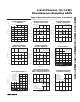
Pin Description
PIN
MAX11047
(TQFN-EP)
MAX11048
(TQFN-EP)
MAX11049
(TQFN-EP)
NAME FUNCTION
1 1 1 DB13 16-Bit Parallel Data Bus Digital Output Bit 13
2 2 2 DB12 16-Bit Parallel Data Bus Digital Output Bit 12
3 3 3 DB11 16-Bit Parallel Data Bus Digital Output Bit 11
4 4 4 DB10 16-Bit Parallel Data Bus Digital Output Bit 10
5 5 5 DB9 16-Bit Parallel Data Bus Digital Output Bit 9
6 6 6 DB8 16-Bit Parallel Data Bus Digital Output Bit 8
7, 21, 50 7, 21, 50 7, 21, 50 DGND Digital Ground
8, 20, 51 8, 20, 51 8, 20, 51 DVDD Digital Supply. Bypass to DGND with a 0.1µF capacitor at each DV
DD
input.
9 9 9 DB7 16-Bit Parallel Data Bus Digital Output Bit 7
10 10 10 DB6 16-Bit Parallel Data Bus Digital Output Bit 6
11 11 11 DB5 16-Bit Parallel Data Bus Digital Output Bit 5
12 12 12 DB4 16-Bit Parallel Data Bus Digital Output Bit 4
13 13 13 DB3/CR3 16-Bit Parallel Data Bus Digital Output Bit 3/Configuration Register Input Bit 3
14 14 14 DB2/CR2 16-Bit Parallel Data Bus Digital Output Bit 2/Configuration Register Input Bit 2
15 15 15 DB1/CR1 16-Bit Parallel Data Bus Digital Output Bit 1/Configuration Register Input Bit 1
16 16 16 DB0/CR0 16-Bit Parallel Data Bus Digital Output Bit 0/Configuration Register Input Bit 0
17 17 17 EOC
Active-Low End of Conversion Output. EOC goes low when conversion is
completed. EOC goes high when a conversion is initiated.
18 18 18 CONVST
Convert Start Input. Rising edge of CONVST ends sample and starts a
conversion on the captured sample. The ADC is in acquisition mode when
CONVST is low and CONVST mode = 0.
19 19 19 SHDN
Shutdown Input. If SHDN is held high, the entire device enters and stays in a
low-current state. Contents of the Configuration register are not lost when in
the shutdown state.
22, 28, 35,
43, 49
22, 28, 35,
43, 49
22, 28, 35,
43, 49
RDC
Reference Buffer Decoupling. Connect all RDC outputs together. Bypass to
AGND with at least an 80µF total capacitance. See the Layout, Grounding,
and Bypassing section.
23, 27, 33,
38, 44, 48
23, 27, 33,
38, 44, 48
23, 27, 33,
38, 44, 48
AGNDS Signal Ground. Connect all AGND and AGNDS inputs together on PWB.
24, 30,
41, 47
24, 30,
41, 47
24, 30,
41, 47
AVDD
Analog Supply Input. Bypass AV
DD
to AGND with a 0.1µF capacitor at each
AV
DD
input.
25, 31,
40, 46
25, 31,
40, 46
25, 31,
40, 46
AGND Analog Ground. Connect all AGND inputs together.
26, 29,
42, 45
26, 45 — I.C. Internally Connected. Connect to AGND
32 29 26 CH0 Channel 0 Analog Input
34 32 29 CH1 Channel 1 Analog Input
36 36 36 REFIO
External Reference Input/Internal Reference Output. Place a 0.1µF capacitor
from REFIO to AGND.