
Datasheet


ICL761X–ICL764X
Single/Dual/Triple/Quad
Operational Amplifiers
24 ______________________________________________________________________________________
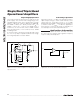
Figure 9. Low Droop Rate Sample and Hold—S2 improves
accuracy and acquisition time by including the voltage drop
across S1 inside the feedback loop. R1 closes the feedback
loop of A1 during the hold phase. The droop rate is [I
BIAS(AZ
)
+ I
LEAK(S1
) + I
LEAK(S2)
]/C
HOLD
.
ICL7622
A1
IH5141
1
⁄
2
ICL7622
A2
1
⁄
2
S/H
CONTROL
INPUT
V
IN
V
OUT
C
HOLD
100kΩ
R
1
S1
S2
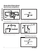
Figure 10. Long-Time Constant Integrator—With R
IN
= 1011
Ω
,
the time constant of this integrator is 100,000s. Since the input
voltage is converted to a current by R
IN
, the input voltage can
far exceed the power-supply range.
-
+
C
INT
R
IN
V
IN
V
OUT
1µF
Figure 11. Pico Ammeter—The response time of this curcuit is
R
FB
x C
FB
, where C
FB
is the stray capacitance between the
output and the inverting terminal of the amplifier.
Figure 12. 60Hz Twin “T“ Notch Filter—The low 1pA bias cur-
rent of the ICL7611 allows use of small 540pF and 270pF
capacitors, even with a notch frequency of 60Hz. The 60Hz
rejection is approximately 40dB.
+
-
CURRENT
SOURCE
C
FB
R
FB
- 10
11
Ω
V
O
= 100mV/pA
+
-
OUTPUT
V
IN
ICL7611
10MΩ10MΩ
270pF270pF
540pF
5MΩ
C
INT
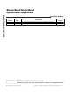
LONG TIME CONSTANT INTEGRATOR
(Detailed Circuit Diagram — Figure 10)
-
+
R
IN
V
OUT
V
IN
Typical Operating Circuit