
Owner manual


DS4830 User’s Guide
97
11.2.3 – I
2
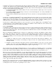
C Slave Interrupt Enable Register (I2CIE_S)
Address: M2[02h]
Bit
15
14
13
12
11
10
9
8
7
6
5
4
3
2
1
0
Name
-
-
-
-
I2CSPIE
-
I2CROIE
I2CGCIE
I2CNACKIE
-
I2CAMIE
I2CTOIE
I2CSTRIE
I2CRXIE
I2CTXIE
I2CSRIE
Reset
0
0
0
0
0
0
0
0
0
0
0
0
0
0
0
0
Access
r
r
r
r
rw
r
rw
rw
rw
r
rw
rw
rw
rw
rw
rw
BIT
NAME
DESCRIPTION
15:12
Reserved
Reserved. The user should write 0 to these bits.
11
I2CSPIE
I
2
C Slave STOP Interrupt Enable. Setting this bit to ‘1’ will cause an interrupt to the CPU when a STOP
condition is detected (I2CSPI=1). Clearing this bit to ‘0’ will disable the STOP detection interrupt.
10
Reserved
Reserved. The user should write 0 to this bit.
9
I2CROIE
I
2
C Slave Receiver Overrun Interrupt Enable. Setting this bit to ‘1’ will cause an interrupt to the CPU when
a receiver overrun condition is detected (I2ROI=1). Clearing this bit to ‘0’ will disable the receiver overrun
detection interrupt.
8
I2CGCIE
I
2
C Slave General Call Interrupt Enable. Setting this bit to '1' will cause an interrupt to the CPU when a
general call is detected (I2CGCI=1). Clearing this bit to '0' will disable the general call interrupt.
7
I2CNACKIE
I
2
C Slave NACK Interrupt Enable. Setting this bit to ‘1’ will cause an interrupt to the CPU when a NACK is
detected (I2CNACKI=1). Clearing this bit to ‘0’ will disable the NACK detection interrupt.
6
-
Reserved. The user should write 0 to this bit.
5
I2CAMIE
I
2
C Slave Address Match Interrupt Enable. Setting this bit to ‘1’ will cause an interrupt to the CPU when
the I
2
C controller detects an address that matches the I2CSLA_S value (I2CAMI=1). Clearing this bit to ‘0’
will disable the address match interrupt.
4
I2CTOIE
I
2
C Slave Timeout Interrupt Enable. Setting this bit to ‘1’ will cause an interrupt to the CPU when an
SMBUS timeout condition is detected (I2CTOI=1). Clearing this bit to ‘0’ will disable the timeout interrupt.
3
I2CSTRIE
I
2
C Slave Clock Stretch Interrupt Enable. Setting this bit to '1' will generate an interrupt to the CPU when
the clock stretch interrupt flag is set (I2CSTRI=1). Clearing this bit will disable the clock stretch interrupt.
2
I2CRXIE
I
2
C Slave Receive Ready Interrupt Enable. Setting this bit to ‘1’ will cause an interrupt to the CPU when
the receive ready interrupt flag is set (I2CRXI=1). Clearing this bit to ‘0’ will disable the receive ready
interrupt.
1
I2CTXIE
I
2
C Slave Transmit Complete Interrupt Enable. Setting this bit to ‘1’ will cause an interrupt to the CPU
when the transmit complete interrupt flag is set (I2CTXI=1). Clearing this bit to ‘0’ will disable the transmit
complete interrupt.
0
I2CSRIE
I
2
C Slave START Interrupt Enable. Setting this bit to ‘1’ will cause an interrupt to the CPU when a START
condition is detected (I2CSRI=1). Clearing this bit to ‘0’ will disable the START detection interrupt.
11.2.4 – I
2
C Slave Address Register (I2CSLA_S)
Address: M2[0Fh]
Bit
15
14
13
12
11
10
9
8
7
6
5
4
3
2
1
0
Name
-
-
-
-
-
-
-
-
A6
A5
A4
A3
A2
A1
A0
I2CMode
Reset
0
0
0
0
0
0
0
0
0
0
1
1
0
1
1
0
Access
r
r
r
r
r
r
r
r
rw
rw
rw
rw
rw
rw
rw
rw
BIT
NAME
DESCRIPTION
15:8
Reserved
Reserved. The user should write 0 to these bits.
7:1
A[6:0]
Slave Address. These address bits contain the address of the I
2
C slave interface. When a match to this
address is detected, the I
2
C controller will automatically acknowledge the host with the I2CACK bit value
and the I2CAMI flag will be set to ‘1’. An interrupt will be generated if enabled.
0
I2CMode
I2C Transfer Mode Select. This bit reflects the actual R/W bit value in current value in I2C transfer and set
by hardware.