
Owner manual


DS4830 User’s Guide
123
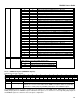
14.3.2.2 – Local Register PWMCGFn
Bit
15
14
13
12
11
10
9
8
7
6
5
4
3
2
1
0
INV
-
ALT_
LOC
PWMEN
-
CLK_SEL
PS32
-
PS4
-
RES
Name
PWMDATA[15:0]
Reset
0
0
0
0
0
0
0
0
0
0
0
0
0
0
0
0
Access
rw
rw
rw
rw
rw
rw
rw
rw
rw
rw
rw
rw
rw
rw
rw
rw
PWMCN REG_SEL = 01b
PWMDATA[15:0] PWMCFGn[15:0]
BIT
NAME
DESCRIPTION
15
INV
Invert PWM Output. When this bit is set to ‘1’, PWM output is inverted for the selected
PWM channel (determined by the PWM_SEL[3:0] bits).
14
-
Reserved. The user should write 0 to this bit.
13
ALT_LOC
Alternate Location: PWM outputs at channels 0 to 7 are multiplexed with the DAC
outputs. By default, the PWM outputs appear at the DAC outputs. When ALT_LOC bit is
set to ‘1’, the PWM outputs will appear at the alternate location (See Table 14-3 for
details).
12
PWMEN
Local Enable: Setting this bit to ‘1’ will enable the individual PWM channel. PWM
operation will be enabled only when both local enable and the Master Enable M_EN in
PWMCN are enabled. Setting this bit to ‘0’ will disable the individual PWM channel.
11:10
Reserved
Reserved. The user should not write to these bits.
9:8
CLK_SEL[1:0]
Clock Select. These bits selects the PWM clock for selected PWM channel (which is
selected by PWM_SEL[3:0] bits).
CLK_SEL
PWM Clock Source
00b
Core Clock
01b
Peripheral Clock
1xb
External Clock
The external clock range is 20MHz to 133MHz.
7
PS32
32-Slot Pulse Spreading: Setting this bit to ‘1’ enables 32-slot pulse spreading if PWM
resolution is 12 bits and PS4 bit is set to ‘1’. When this bit and PS4 are set to ‘1’, the PWM
period is divided into 32 slots of equal length. Setting this bit to ‘0’ disables the 32-slot
pulse spreading.
6:5
Reserved
Reserved. The user should not write to these bits.
4
PS4
4-Slot Pulse Spreading: Setting this bit to ‘1’ enables 4-slot pulse spreading. When this
bit is set to ‘1’, the PWM period is divided into 4 slots of equal length. When this bit is set
to ‘0’, it disables 4-slot and 32-slot pulse spreading.
3
Reserved
Reserved. The user should not write to this bit.
2:0
RES[2:0]
Resolution Select. These bits are used to configure PWM resolution (in bits) for selected
PWM channel (which is selected by PWM_SEL[3:0] bits). The PWM Frame frequency is
determined by the clock Frequency programmed and the resolution selected.
N
FrequencyClockPWM
FrequencyFramePWM
2
where n is the selected resolution.
RES[2:0]
PWM Resolution bits
000b
7
001b
8
010b
9
011b
10
100b
11
101b
12
110b
12
111b
12