
Datasheet


DS26518 8-Port T1/E1/J1 Transceiver
211 of 312
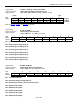
Register Name:
T1TSLC1, T1TSLC2, T1TSLC3 (T1 Mode)
Register Description:
Transmit SLC-96 Data Link Registers 1 to 3
Register Address:
164h, 165h, 166h + (200h x (n - 1)) : where n = 1 to 8
(MSB) (LSB)
Bit # 7 6 5 4 3 2 1 0
Name C8 C7 C6 C5 C4 C3 C2 C1
T1TSLC1
M2 M1 S=0 S=1 S=0 C11 C10 C9
T1TSLC2
S=1 S4 S3 S2 S1 A2 A1 M3
T1TSLC3
Note: See E1TAF, E1TNAF, and E1TSiAF for E1 Mode.
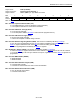
Register Name:
E1TAF (E1 Mode)
Register Description:
Transmit Align Frame Register
Register Address:
164h + (200h x (n - 1)) : where n = 1 to 8
Bit # 7 6 5 4 3 2 1 0
Name Si 0 0 1 1 0 1 1
Default 0 0 0 1 1 0 1 1
Bit 7: International Bit (Si)
Bit 6: Frame Alignment Signal Bit (0)
Bit 5: Frame Alignment Signal Bit (0)
Bit 4: Frame Alignment Signal Bit (1)
Bit 3: Frame Alignment Signal Bit (1)
Bit 2: Frame Alignment Signal Bit (0)
Bit 1: Frame Alignment Signal Bit (1)
Bit 0: Frame Alignment Signal Bit (1)
Register Name:
E1TNAF (E1 Mode)
Register Description:
Transmit Non-Align Frame Register
Register Address:
165h + (200h x (n - 1)) : where n = 1 to 8
Bit # 7 6 5 4 3 2 1 0
Name Si 1 A Sa4 Sa5 Sa6 Sa7 Sa8
Default 0 1 0 0 0 0 0 0
Bit 7: International Bit (Si)
Bit 6: Frame Non-Alignment Signal Bit (1)
Bit 5: Remote Alarm (Used to Transmit the Alarm) (A)
Bit 4: Additional Bit 4 (Sa4)
Bit 3: Additional Bit 5 (Sa5)
Bit 2: Additional Bit 6 (Sa6)
Bit 1: Additional Bit 7 (Sa7)
Bit 0: Additional Bit 8 (Sa8)