
Datasheet


DS2480B
Maxim Integrated ........................................................................................................................................................................................... 24
HARDWARE APPLICATION EXAMPLES
This section discusses five typical application scenarios. The DS2480B can be configured for EPROM
programming as well as for 5V operation only.
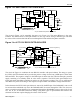
OUTPUT FILTERING
As described in the CONTROLLED EDGES section, the DS2480B employs an active pullup on the rising
edges of the 1-Wire waveform.
Excessive noise on the 1-Wire line in the region of the pullup trip voltage, V
IAPTO,
can cause an
undesirable trip of the active pullup, which can disrupt 1-Wire communication. External R-C filtering as
shown in Figure 10 should be added to all DS2480B configurations with the exception of those that
perform EPROM programming.
For EPROM programming configurations the R-C filter cannot be used due to the voltage drop that will
develop across the 100Ω resistor during programming.
Figure 10. R-C FILTERING
1-Wire Bus
Return
5 V
5V Operation Only
GND
1-W
POL
VDD
VPP
RXD
TXD
DS2480B
470 pF
See Application Note 148
for additional information.
62 Ohms
DS9503
To protect the 1-Wire port of the DS2480B from electrostatic discharge it is recommended to use a low-
capacitance ESD protection diode, such as the DS950x devices. For 5V operation a single device is
sufficient. For EPROM programming two DS950x devices must be connected in series to achieve a high
enough breakdown voltage.
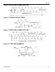
Figures 11a-c are examples of connecting the DS2480B directly to a UART or RS232C interface. The
circuit becomes more complex if a 1-Wire bus is to be interfaced to a port that provides and expects
inverted signals, but does not necessarily meet the RS232C (±12V) standard (Figure 11b).