
Datasheet


DS2408
38 of 39
APPLICATIONS INFORMATION
Power-up timing
The DS2408 is sensitive to the power-on slew rate and can inadvertently power up with a test mode
feature enabled. When this occurs, the P0 port does not respond to the Channel Access Write command.
For most reliable operation, it is recommended to disable the test mode after every power-on reset using
the Disable Test Mode sequence shown below. The 64-bit ROM code must be transmitted in the same bit
sequence as with the Match ROM command, i.e., least significant bit first. This precaution is
recommended in parasite power mode (V
CC
pin connected to GND) as well as with V
CC
power.
Disable Test Mode
RST PD 96h <64-bit DS2408 ROM Code> 3Ch RST PD
Power-up State of P0 to P7
When the DS2408 powers up, the state of the I/O pins P0 to P7 is indeterminate. This behavior may not
be acceptable for some applications. To ensure that P0 to P7 power up in the "off" state, it is necessary to
have a suitable power-on-reset circuit, such as the DS1811, or a supervisor IC connected to the RSTZ pin.
RSTZ Pin
When not configured as
STRB
output, the RSTZ pin is to be connected to V
CC
, directly or through a
resistor. A local V
CC
supply can be created by taking energy from the 1-Wire line, as shown in Figure 21.
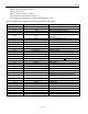
PACKAGE INFORMATION
For the latest package outline information and land patterns, go to www.maxim-ic.com/packages. Note
that a “+”, “#”, or “-” in the package code indicates RoHS status only. Package drawings may show a
different suffix character, but the drawing pertains to the package regardless of RoHS status.
PACKAGE TYPE PACKAGE CODE OUTLINE NO. LAND PATTERN NO.
16 SO (150 mils) S16+5
21-0041 90-0097