
Datasheet


DS2155
89 of 238
16.2 Transmit Signaling
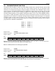
Figure 16-2. Simplified Diagram of Transmit Signaling Path
16.2.1 Processor-Based Mode
In processor-based mode, signaling data is loaded into the transmit signaling registers (TS1–TS16) by the
host interface. On multiframe boundaries, the contents of these registers are loaded into a shift register for
placement in the appropriate bit position in the outgoing data stream. The user can employ the transmit
multiframe interrupt in status register 4 (SR4.4) to know when to update the signaling bits. The user need
not update any transmit signaling register for which there is no change-of-state for that register.
Each transmit signaling register contains the robbed-bit signaling (T1) or TS16 CAS signaling (E1) for
two time slots that are inserted into the outgoing stream, if enabled to do so through T1TCR1.4 (T1
mode) or E1TCR1.6 (E1 mode). In T1 mode, only TS1–TS12 are used.
Signaling data can be sourced from the TS registers on a per-channel basis by using the software
signaling insertion enable registers, SSIE1–SSIE4.
16.2.1.1 T1 Mode
In T1 ESF framing mode, there are four signaling bits per channel (A, B, C, and D). TS1–TS12 contain a
full multiframe of signaling data. In T1 D4 framing mode, there are only two signaling bits per channel
(A and B). In T1 D4 framing mode, the framer uses the C and D bit positions as the A and B bit positions
for the next multiframe. In D4 mode, two multiframes of signaling data can be loaded into TS1–TS12.
The framer loads the contents of TS1–TS12 into the outgoing shift register every other D4 multiframe. In
D4 mode, the host should load new contents into TS1–TS12 on every other multiframe boundary and no
later than 120µs after the boundary.
TRANSMIT
SIGNALING
REGISTERS
SIGNALING
BUFFERS
PER-CHANNEL
CONTROL
TSER
TSIG
T1/E1 DATA
STREAM
PER-CHANNEL
CONTROL
SSIE1 - SSIE4
B7
T1TCR1.4
1
0
0
1
0
1
PCPR.3
ONLY APPLIES TO T1 MODE