
Datasheet


DS2155
180 of 238
27. PAYLOAD ERROR-INSERTION FUNCTION (T1 MODE ONLY)
An error-insertion function is available in the DS2155 and is used to create errors in the payload portion
of the T1 frame in the transmit path. This function is only available in T1 mode. Errors can be inserted
over the entire frame or the user can select which channels are to be corrupted. Errors are created by
inverting the last bit in the count sequence. For example, if the error rate 1 in 16 is selected, the 16th bit is
inverted. F-bits are excluded from the count and are never corrupted. Error rate changes occur on frame
boundaries. Error-insertion options include continuous and absolute number with both options supporting
selectable insertion rates.
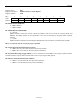
Table 27-A. Transmit Error-Insertion Setup Sequence
STEP ACTION
1 Enter desired error rate in the ERC register. Note: If ER3 through ER0 = 0, no errors
are generated even if the constant error-insertion feature is enabled.
2A
or
2B
For constant error insertion, set CE = 1 (ERC.4).
For a defined number of errors:
– Set CE = 0 (ERC.4)
– Load NOE1 and NOE2 with the number of errors to be inserted
– Toggle WNOE (ERC.7) from 0 to 1 to begin error insertion