
Datasheet


DS21348/DS21Q348
31 of 76
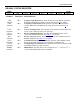
CCR3 (02H): COMMON CONTROL REGISTER 3
(MSB)
(LSB)
TUA1 ATUA1 TAOZ TPRBSE TLCE LIRST IBPV IBE
SYMBOL POSITION DESCRIPTION
TUA1 CCR3.7 Transmit Unframed All Ones. The polarity of this bit is set such that the
device will transmit an all ones pattern on power-up or device reset. This
bit must be set to a one to allow the device to transmit data. The
transmission of this data pattern is always timed off of the JACLK (See
Figure 1-1).
0 = transmit all ones at TTIP and TRING
1 = transmit data normally
ATUA1 CCR3.6 Automatic Transmit Unframed All Ones. Automatically transmit an
unframed all ones pattern at TTIP and TRING during a receive carrier loss
(RCL) condition or receive all ones condition.
0 = disabled
1 = enabled
TAOZ CCR3.5 Transmit Alternate Ones and Zeros. Transmit a …101010… pattern at
TTIP and TRING. The transmission of this data pattern is always timed
off of TCLK (Figure 1-1).
0 = disabled
1 = enabled
TPRBSE CCR3.4 Transmit PRBS Enable. Transmit a 2
15
- 1 (E1) or a 2
20
- 1 (T1) PRBS at
TTIP and TRING (Figure 1-3).
0 = disabled
1 = enabled
TLCE CCR3.3 Transmit Loop Code Enable. Enables the transmit side to transmit the
loop up code in the Transmit Code Definition registers (TCD1 and
TCD2). See Section 4 and Figure 1-3 for details.
0 = disabled
1 = enabled
LIRST CCR3.2 Line Interface Reset. Setting this bit from a zero to a one will initiate an
internal reset that resets the clock recovery state machine and re-centers
the jitter attenuator. Normally this bit is only toggled on power-up. Must
be cleared and set again for a subsequent reset.
IBPV CCR3.1 Insert BPV. A 0 to 1 transition on this bit will cause a single BiPolar
Violation (BPV) to be inserted into the transmit data stream. Once this bit
has been toggled from a 0 to a 1, the device waits for the next occurrence
of three consecutive ones to insert the BPV. This bit must be cleared and
set again for a subsequent error to be inserted (Figure 1-3).
IBE CCR3.0 Insert Bit Error. A 0 to 1 transition on this bit will cause a single logic
error to be inserted into the transmit data stream. This bit must be cleared
and set again for a subsequent error to be inserted (Figure 1-3).