
Datasheet


The alarm bytes can be used in two ways. First, when
the alarm time is written in the appropriate hours, min-
utes, and seconds alarm locations, the alarm interrupt
is initiated at the specified time each day, if the alarm
enable bit is high. In this mode, the “0” bits in the alarm
registers and the corresponding time registers must
always be written to 0 (see Table 3A and 3B). Writing
the 0 bits in the alarm and/or time registers to 1 can
result in undefined operation.
The second use condition is to insert a “don’t care”
state in one or more of the alarm bytes. The don’t care
code is any hexadecimal value from C0 to FF. The two
most significant bits of each byte set the don’t care
condition when at logic 1. An alarm will be generated
each hour when the “don’t care” bits are set in the
hours byte. Similarly, an alarm is generated every
minute with don’t care codes in the hours and minute
alarm bytes. An alarm is generated every second with
don’t care codes in the hours, minutes, and seconds
alarm bytes.
All 128 bytes can be directly written or read except for
the following:
1) Registers C and D are read-only.
2) Bit 7 of register A is read-only.
3) The MSB of the seconds byte is read-only.
DS17285/DS17287/DS17485/DS17487/DS17885/DS17887
Real-Time Clocks
____________________________________________________________________ 13
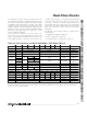
Table 3A. Time, Calendar, and Alarm Data Modes—BCD Mode (DM = 0)
Note: Unless otherwise specified, the state of the registers is not defined when power is first applied. Except for the seconds regis-
ter, 0 bits in the time and date registers can be written to 1, but can be modified when the clock updates. 0 bits should always be
written to 0 except for alarm mask bits.
ADDRESS BIT 7 BIT 6 BIT 5 BIT 4 BIT 3 BIT 2 BIT 1 BIT 0 FUNCTION RANGE
00h 0 10 Seconds Seconds Seconds 00–59
01h 0 10 Seconds Seconds Seconds Alarm 00–59
02h 0 10 Minutes Minutes Minutes 00–59
03h 0 10 Minutes Minutes Minutes Alarm 00–59
AM/PM 0 10 Hour
04h
0
0
10 Hour
Hours Hours
1–12 +AM/PM
00–23
AM/PM 0 10 Hour
05h
0
0
10 Hour
Hours Hours Alarm
1–12 +AM/PM
00–23
06h 0 0 0 0 0 Day Day 01–07
07h 0 0 10 Date Date Date 01–31
08h 0 0 0 10 Month Month Month 01–12
09h 10 Year Year Year 00–99
0Ah UIP DV2 DV1 DV0 RS3 RS2 RS1 RS0 Control —
0Bh SET PIE AIE UIE SQWE DM 24/12 DSE Control —
0Ch IRQF PF AF UF 0 0 0 0 Control —
0Dh VRT 0 0 0 0 0 0 0 Control —
Bank 1, 48h 10 Century Century Century 00–99
Bank 1, 49h 10 Date Date Date Alarm 01–31