
Datasheet


DS1501/DS1511 Y2KC Watchdog Real-Time Clocks
15 of 22
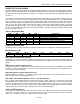
Control A Register (0Eh)
Bit 7
Bit 6
Bit 5
Bit 4
Bit 3
Bit 2
Bit 1
Bit 0
BLF1
BLF2
PRS
PAB
TDF
KSF
WDF
IRQF
BLF1, Valid RAM and Time Bit 1 (0Eh Bit 7); BLF2, Valid RAM and Time Bit 2 (0Eh Bit 6)
These status bits give the condition of any batteries attached to the V
BAT
or V
BAUX
pins. The DS1501/DS1511
constantly monitor the battery voltage of the backup-battery sources (V
BAT
and V
BAUX
). The BLF1 and BLF2 bits are
set to 1 if the battery voltages on V
BAT
and V
BAUX
are less than V
BLF
(typ), otherwise BLF1 and BLF2 bits are 0.
BLF1 reflects the condition of V
BAT
with BLF2 reflecting V
BAUX
. If either bit is read as 1, the voltage on the respective
pin is inadequate to maintain the RAM memory or clock functions. These bits are read only.
PRS, Reset Select Bit (0Eh Bit 5)
When set to 0, the PWR pin is set high-Z when the DS1501/DS1511 go into power-fail. When set to 1, the PWR pin
remains active upon entering power-fail.
PAB, Power Active-Bar Control Bit (0Eh Bit 4)
When this bit is 0, the PWR pin is in the active-low state. When this bit is 1, the PWR pin is in the high-impedance
state. The user can write this bit to 1 or 0. If either TDF and TPE = 1 or KSF = 1, the PAB bit is cleared to 0. This bit
can be read or written.
TDF, Time-of-Day/Date Alarm Flag (0Eh Bit 3)
A 1 in the TDF bit indicates that the current time has matched the alarm time. If the TIE bit is also 1, the IRQ pin
goes low and a 1 appears in the IRQF bit. This bit is cleared by reading the register or writing it to 0.
KSF, Kickstart Flag (0Eh Bit 2)
This bit is set to a 1 when a kickstart condition occurs or when the user writes it to 1. If the KIE bit is also 1, the IRQ
pin goes low and a 1 appears in the IRQF bit. This bit is cleared by reading the register or writing it to 0.
WDF, Watchdog Flag (0Eh Bit 1)
If the processor does not access the DS1501/DS1511 with a write within the period specified in addresses 0Ch and
0Dh, the WDF bit is set to 1. WDF is cleared by writing it to 0.
IRQF, Interrupt Request Flag (0Eh Bit 0)
The interrupt request flag (IRQF) bit is set to 1 when one or more of the following are true:
TDF = TIE = 1
KSF = KIE = 1
WDF = WDE = 1
i.e., IRQF = (TDF x TIE) + (KSF x KIE) + (WDF x WDE)
Any time the IRQF bit is 1, the IRQ pin is driven low.
Clearing IRQ and Flags
The time-of-day/date alarm flag (TDF), watchdog flag (WDF), kickstart flag (KSF), and interrupt request flag (IRQF)
are cleared by reading the flag register (0Eh). The address must be stable for a minimum of 15ns while CE and OE
are active. After the address stable requirement has been met, either a change in address, a rising edge of OE, or
a rising edge of CE causes the flags to be cleared. The IRQ pin goes inactive after the IRQF flag is cleared. TDF
and WDF can also be cleared by writing to 0.