
Datasheet


DS1501/DS1511 Y2KC Watchdog Real-Time Clocks
9 of 22
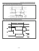
PIN DESCRIPTION
PIN
NAME FUNCTION
SO EDIP TSOP
1 1 8
PWR
Active-Low Power-On Output (Open Drain). This output, if used, is normally
connected to power-supply control circuitry. This pin requires a pullup resistor
connected to a positive supply to operate correctly.
2, 3 — 9, 10 X1, X2
Connections for Standard 32.768kHz Quartz Crystal. For greatest accuracy, the
DS1501 must be used with a crystal that has a specified load capacitance of either
6pF or 12.5pF. The crystal select (CS) bit in control register B is used to select
operation with a 6pF or 12.5pF crystal. The crystal is attached directly to the X1 and
X2 pins. There is no need for external capacitors or resistors. An external 32.768kHz
oscillator can also drive the DS1501. In this configuration, the X1 pin is connected to
the external oscillator signal and the X2 pin is floated. For more information about
crystal selection and crystal layout considerations, refer to
Application Note 58:
Crystal Considerations with Dallas Real-Time Clocks. See Figure 9. An enable bit in
the month register controls the oscillator. Oscillator startup time is highly dependent
upon crystal characteristics, PC board leakage, and layout. High ESR and excessive
capacitive loads are the major contributors to long startup times. A circuit using a
crystal with the recommended characteristics and proper layout usually starts within
one second.
4 4 11
RST
Active-Low Reset Output. (Open Drain). This output, if used, is normally connected
to a microprocessor-reset input. This pin requires a pull up resistor connected to a
positive supply to operate correctly. When RST is active, the device is not
accessible.
5 5 12 IRQ
Active-Low Interrupt Output (Open Drain). This output, if used, is normally connected
to a microprocessor interrupt input. This pin requires a pullup resistor connected to a
positive supply to operate correctly.
6–10 6–10 13–17 A4–A0 Address Inputs. Selects one of 17 register locations.
11–13,
15–19
11–13,
15–19
18–20,
22–26
DQ0–DQ7 Data Input/Output. I/O pins for 8-bit parallel data transfer.
14, 21 14 21, 28 GND
Ground. DC power is applied to the device on these pins. V
CC
is the positive terminal.
When power is applied within the normal limits, the device is fully accessible and
data can be written and read. When V
CC
drops below the normal limits, reads and
writes are inhibited. As V
CC
drops below the battery voltage, the RAM and
timekeeping circuits are switched over to the battery.
22 22 1
OE
Output-Enable Input. Active-low input that enables DQ0–DQ7 for data output from
the device.
20 20 27 CE
Chip-Enable Input. Active-low input to enable the device.
23 23 2 SQW
Square-Wave Output. When enabled, the SQW pin outputs a 32.768kHz square
wave. If the square wave (E32K) and battery backup 32kHz (BB32) bits are enabled,
power is provided by V
BAUX
when V
CC
is absent.
24 24 3 KS
Active-Low Kickstart Input. This pin is used to wake up a system from an external
event, such as a key closure. The KS pin is normally connected using a pullup
resistor to V
BAUX
. If the KS function is not used, connect to ground.
25 — 4 V
BAT
Battery Input for Any Standard 3V Lithium Cell or Other Energy Source. Battery
voltage must be held between 2.5V and 3.7V for proper operation. UL recognized to
ensure against reverse charging current when used with a lithium battery.
www.maximintegrated.com/TechSupport/QA/ntrl.htm If not used, connect to ground.
26 26 5 V
BAUX
Auxiliary Battery Input for Any Standard 3V Lithium Cell or Other Energy Source.
Battery voltage must be held between 2.5V and 3.7V for proper operation. UL
recognized to ensure against reverse charging current when used with a lithium
battery,
www.maximintegrated.com/TechSupport/QA/ntrl.htm. If not used, connect to
ground.
27 27 6 WE
Write-Enable Input. Active-low input that enables DQ0–DQ7 for data input to the
device.
28 28 7 V
CC
DC Power. V
CC
is the positive terminal. When power is applied within the normal
limits, the device is fully accessible and data can be written and read. When V
CC
drops below the normal limits, reads and writes are inhibited. As V
CC
drops below the
battery voltage, the RAM and timekeeping circuits are switched over to the battery.
—
2, 3, 21,
25
— N.C. No Connect