
Datasheet


I
2
C RTC/Supervisor with Trickle Charger
and 512 Bytes EEPROM
4 Maxim Integrated
DS1388
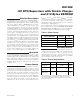
AC ELECTRICAL CHARACTERISTICS
(V
CC
= V
CC(MIN)
to V
CC(MAX)
, T
A
= -40°C to +85°C, unless otherwise noted.) (Note 2)
PARAMETER SYMBOL CONDITION MIN TYP MAX UNITS
Fast mode 100 400
SCL Clock Frequency f
SCL
Standard mode 0 100
kHz
Fast mode 1.3
Bus Free Time Between a STOP
and START Condition
t
BUF
Standard mode 4.7
μs
Fast mode 0.6
Hold Time (Repeated) START
Condition (Note 12)
t
HD:STA
Standard mode 4.0
μs
Fast mode 1.3
LOW Period of SCL Clock t
LOW
Standard mode 4.7
μs
Fast mode 0.6
HIGH Period of SCL Clock t
HIGH
Standard mode 4.0
μs
Fast mode 0.6
Setup Time for a Repeated
START Condition
t
SU:STA
Standard mode 4.7
μs
Fast mode 0 0.9
Data Hold Time (Notes 13, 14) t
HD:DAT
Standard mode 0
μs
Fast mode 100
Data Setup Time (Note 15) t
SU:DAT
Standard mode 250
ns
Fast mode 300
Rise Time of Both SDA and SCL
Signals (Note 16)
t
R
Standard mode
20 +
0.1C
B
1000
ns
Fast mode 300
Fall Time of Both SDA and SCL
Signals (Note 16)
t
F
Standard mode
20 +
0.1C
B
300
ns
Fast mode 0.6
Setup Time for STOP Condition t
SU:STO
Standard mode 4.0
μs
Capacitive Load for Each Bus
Line
C
B
(Note 16) 400 pF
I/O Capacitance (SDA, SCL, RST) C
I/O
+25°C 10 pF
Pushbutton Debounce PB
DB
160 180 ms
Reset Active Time t
RST
160 180 ms
EEPROM Write Cycle Time t
WEE
8 10 ms
Oscillator Stop Flag (OSF) Delay t
OSF
(Note 17) 20 ms