
User guide


UG_12xxF_037 73S12xxF USB-CCID Host GUI Users Guide
Rev. 1.1 13
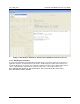
2.1.6 KeyPad Tests Frame
The KeyPad Tests frame contains two sub-frames, one that displays a six row by a five column image
matrix and the other to configure the keypad matrix. Figure 9 shows the KeyPad Tests Frame. The
number of rows and columns configuration must be configured before any keypad operations can be
initiated. The image matrix remains grayed until the configuration is sent to the device. Clicking the
Send button sends the configuration packet. The keypad image matrix enables those keys as defined by
the Rows and Columns settings. The selection is justified at the upper left as being row one and column
one. The Configuration button will be de-selected and sub-frame will be disabled. Once the
configuration has been set up, it will maintain that configuration until the Configuration button is selected
again. The Single Key and Multiple Keys buttons are enabled after the keypad is configured.
Figure 9: KeyPad Tests Frame
2.1.6.1 Single Key Button
Clicking the Single Key button enables the single key function in the device. This function waits for a
keystroke on a specific key location. All other keys are ignored. The corresponding key location on the
image can be clicked. This turns that key location a shade of Blue indicating that the corresponding key
location on the devices keypad is expected to be pressed by the user. Clicking the Send button enables
this function. All other frames are disabled. The device waits indefinitely until a keystroke is performed
on the specific key location. When this occurs, the response message is noted in the transaction window
and all frames are restored to the state before the single key command was performed.
2.1.6.2 Multiple Keys Button
Selecting the Multiple Keys button enables the multiple keys function in the device. This function waits
for a specific number (n) of keystrokes and returns a log of the keystrokes in the response after the nth
keystroke. The image matrix locations is displayed in the transaction window as well as embedded in the
command response packet.
2.1.7 LED Frame
The LED functionality is active only in CCID mode and is not active in DFU mode. The LED frame
contains LED number selection, three choices for the LED light intensity (Normal, Dim and Bright), blink
rate menu bar selection (or type in) and three LED ON, OFF and Blink Command Icons. LED number is
0 as default. The LED ON and LED OFF Commands would turn ON and OFF the LED, respectively.
The LED brightness can be checked from the three choices. The LED blink rate range is from 1 to 255;
each count is equivalent to 100 msec LED blink duration. The default blink value is 5 which is equivalent
to 500 msec (5 X 100 msec) blink duration. When the LED brightness and the blink rate are selected,
then pressing the LED Blink Command would activate the LED and it would blink at inputted rate. When
the Host GUI starts, the LED would be ON or OFF depending if a Smart Card is in or not, respectively. In
order to for the LED start blinking, at least one Smart Card needs to be inserted and connected (HOST
GUI Connect command is pressed).