
User Manual


9 ENGLISH
ASSEMBLY
CAUTION: Always be sure that the tool is
switched off and unplugged before carrying out
any work on the tool.
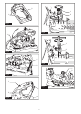
Opening center cap type safety
guard
Country specic
Forthetoolsequippedwithcentercaptypesafetyguard,
loosentheclampingscrewrstthenraisetheguard.
►Fig.11: 1.Clampingscrew
Opening European type safety
guard
Country specic
ForthetoolsequippedwithEuropeantypesafetyguard,loosen
theclampingscrewrstthenopentheguardasshown.
►Fig.12: 1.Clampingscrew
►Fig.13
►Fig.14
Removing or installing cut-off wheel
CAUTION: Be sure to tighten the toolless
clamp or hex bolt securely.Insufcienttightening
mayresultinsevereinjury.Whentighteningthehex
bolt,usethesocketwrenchprovidedwiththetoolto
assure proper tightening.
CAUTION: Always use only the proper inner
and outer anges which are provided with the
tool.
CAUTION: Always lower the safety guard
after replacing the wheel.
►Fig.15: 1.Innerange2. Ring 3. O-ring 4.Cut-off
wheel 5.Outerange6. Toolless clamp /
Hexbolt
For LW1400
Raise the safety guard. Turn the toolless clamp coun-
terclockwise while holding down the shaft lock. Then
removethetoollessclamp,outerangeandcut-off
wheel. When removing the cut-off wheel, do not remove
theinnerangeaswellastheringandO-ring.
►Fig.16: 1. Shaft lock 2. Toolless clamp
To install the cut-off wheel, follow the removal proce-
duresinreverse.Makesuretottheholeofcut-off
wheel to the ring and return the safety guard.
For LW1401
Raisethesafetyguard.Turnthehexboltcounterclock-
wise using a socket wrench while holding down the
shaftlock.Thenremovethehexbolt,outerangeand
wheel.
►Fig.17: 1. Shaft lock 2.Hexbolt
To install the wheel, follow the removal procedures in
reverse.Makesuretottheholeofcut-offwheeltothe
ring and return the safety guard.
OPERATION
CAUTION: Proper handle pressure during
cutting and maximum cutting efciency can
be determined by the amount of sparks that is
produced while cutting. Do not force the cut
by applying excessive pressure on the handle.
Reducedcuttingefciency,prematurewheelwear,as
wellas,possibledamagetothetool,cut-offwheelor
workpiece may result.
Holdthehandlermly.Switchonthetoolandwaituntil
thewheelattainsfullspeedbeforeloweringgently
into the cut. When the wheel contacts the workpiece,
graduallybeardownonthehandletoperformthecut.
When the cut is completed, switch off the tool and wait
until the wheel has come to a complete stop before
returning the handle to the fully elevated position.
Cutting capacity
Maximum cutting capacity varies depending on the
cutting angle and workpiece shape.
Max. cutting capacity with a brand-new cut-off
wheel
Cutting angle /
Workpiece shape
90° 45°
127 mm 127 mm
115 x 130 mm
102 x 194 mm
70 x 233 mm
115 x 103 mm
119 x 119 mm 106 x 106 mm
137 x 137 x 10 mm 100 x 100 x 10 mm
Securing workpiece
CAUTION: Always place the thread holder on
the shaft threads when securing the workpiece.
Failuretodosomayresultininsufcientsecuringof
theworkpiece.Thiscouldcausetheworkpiecetobe
ejectedorcauseadangerousbreakageofthewheel.
Whilethethreadholderislifted,theviseplatecanbe
moved in and out quickly. To grip a workpiece, push the
handle until the vise plate contacts the workpiece then
return the thread holder. Turn the handle clockwise until
the workpiece is securely retained.
►Fig.18: 1. Handle 2. Thread holder 3. Vise plate
Whenthecut-offwheelhasworndownconsiderably,
placeaspacerblockbehindtheworkpieceasshown