
Instruction manual


5
ENGLISH
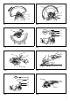
Explanation of general view
SPECIFICATIONS
• Due to our continuing program of research and development, the specifications herein are subject to change without
notice.
• Note: Specifications may differ from country to country.
Symbols
END202-4
The following show the symbols used for the equipment.
Be sure that you understand their meaning before use.
............. Read instruction manual.
............. DOUBLE INSULATION
............. Wear safety glasses.
Intended use
ENE048-1
The tool is intended for grinding, sanding and cutting of
metal and stone materials without the use of water.
Power supply
ENF002-1
The tool should be connected only to a power supply of
the same voltage as indicated on the nameplate, and can
only be operated on single-phase AC supply. They are
double-insulated in accordance with European Standard
and can, therefore, also be used from sockets without
earth wire.
SPECIFIC SAFETY RULES GEB033-1
DO NOT let comfort or familiarity with product (gained
from repeated use) replace strict adherence to grinder
safety rules. If you use this tool unsafely or
incorrectly, you can suffer serious personal injury.
1. Safety Warnings Common for Grinding, Sanding,
Wire Brushing, or Abrasive Cutting-Off
Operations:
2. This power tool is intended to function as a
grinder, sander, wire brush or cut-off tool. Read all
safety warnings, instructions, illustrations and
specifications provided with this power tool.
Failure to follow all instructions listed below may result
in electric shock, fire and/or serious injury.
3. Operations such as polishing are not
recommended to be performed with this power
tool. Operations for which the power tool was not
designed may create a hazard and cause personal
injury.
4. Do not use accessories which are not specifically
designed and recommended by the tool
manufacturer. Just because the accessory can be
attached to your power tool, it does not assure safe
operation.
5. The rated speed of the accessory must be at least
equal to the maximum speed marked on the power
tool. Accessories running faster than their rated
speed can break and fly apart.
6. The outside diameter and the thickness of your
accessory must be within the capacity rating of
your power tool. Incorrectly sized accessories
cannot be adequately guarded or controlled.
7. The arbour size of wheels, flanges, backing pads
or any other accessory must properly fit the
spindle of the power tool. Accessories with arbour
holes that do not match the mounting hardware of the
power tool will run out of balance, vibrate excessively
and may cause loss of control.
8. Do not use a damaged accessory. Before each use
inspect the accessory such as abrasive wheels for
chips and cracks, backing pad for cracks, tear or
excess wear, wire brush for loose or cracked
wires. If power tool or accessory is dropped,
inspect for damage or install an undamaged
accessory. After inspecting and installing an
1. Shaft lock
2. Lock button/Lock-off button
3. Switch trigger (type A)
4. Lock lever
5. Switch trigger (type B)
6. Indication lamp
7. Protrusion of loop handle
8. Matching hole in gear housing
9. Loop handle
10. Hex wrench
11. Bolt
12. Wheel guard
13. Screw
14. Bearing box
15. Lever
16. Lock nut
17. Depressed center grinding wheel
Multi-disc
18. Inner flange
19. Lock nut wrench
20. Abrasive cut-off wheel
21. Wheel guard for cut-off wheel
22. Exhaust vent
23. Inhalation vent
24. Limit mark
25. Brush holder cap
26. Screwdriver
Model GA5020 GA5021 GA5021C GA6020 GA6021 GA6021C
Depressed center wheel diameter 125 mm 125 mm 125 mm 150 mm 150 mm 150 mm
Spindle thread M14 M14 M14 M14 M14 M14
No load speed (n
o) / Rated speed (n)
11,000 min
-1
11,000 min
-1
10,000 min
-1
10,000 min
-1
10,000 min
-1
9,000 min
-1
Overall length 356 mm 384 mm 390 mm 356 mm 384 mm 390 mm
Net weight 2.2 kg 2.3 kg 2.4 kg 2.2 kg 2.3 kg 2.4 kg
Safety class /II