
Operation Instructions

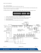


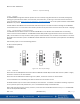
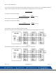


Table Of Contents
- 1 General Safety Information
- 2 Use Instructions and Limitations
- 3 Installation Instructions
- 3.1 Location & Mounting
- 3.2 Installation
- 3.2.1 General Wiring Information
- 3.2.2 Installation Diagram
- 3.2.3 Power Connection
- 3.2.4 Remote Sensor Connection
- 3.2.4.1 MRS-485 Connection and Operation
- 3.2.4.2 Connection
- 3.2.4.3 Dip Switches and Addressing
- 3.2.4.4 Topology
- 3.2.4.5 Line Termination – End of Line Resistor
- 3.2.4.6 Baud Rate
- 3.2.4.7 Wire Selection
- 3.2.4.8 Wire Length
- 3.2.4.9 Grounding
- 3.2.4.10 External Power Supply
- 3.2.4.11 Power Wire
- 3.2.4.12 4-20mA Connection
- 3.2.4.13 Relay Connection
- 3.2.5 Remote Relay Connection
- 3.2.6 Remote Relay Operation
- 3.2.7 Horn & Strobe Connection
- Figure 3-4 – System Wiring Diagram
- 4 Operations
- 4.1 Power up
- 4.2 User Interface
- 4.3 Normal Status Display
- 4.4 ALARM, WARNING, and TROUBLE Status Display
- 4.5 Ventilation Control
- 4.6 Main Menu
- Figure 4-6 –
- 4.6.1 CONFIGURE SYSTEM?
- 4.6.2 MANUAL CONFIGURE?
- 4.6.3 CONFIGURE RELAYS, H/S, BUZZER?
- 4.6.4 COMMUNICATION?
- 4.6.5 VIEW SENSORS?
- 4.6.6 DATE/TIME – PASSWORD?
- 4.6.7 EVENTS?
- 4.6.8 TECHNICAL SUPPORT?
- 5 BACnet
- 5.1 General Information
- Table 5-1 – Types of Detector
- Table 5-2 – Engineering Unit
- Table 5-3 – BACnet Objects for Group Settings of all Zone
- Table 5-4 – BACnet Object for Detector Reading
- Table 5-5 – Bit Assignment for Zone[N]. mode value
- Table 5-6 – BACnet Objects for Zone Configuration
- Table 5-7 – BACnet Objects for DVP-1200 Outputs
- 5.1 General Information
- 6 Testing & Maintenance
- 7 Appendix A – Table of Figures
- 8 Appendix C – Replacement Parts
- 9 Appendix D – Setup Record
- 10 Macurco Gas Detection Product limited warranty
- Blank Page
- Blank Page
- Blank Page

Macurco
TM
DVP-1200 Manual
REV – 1.3.1 [34-8708-4770-7 ] 12 | Page
Note: For ethernet connection, use surge protector (Model: DTK-MRJPOE manufactured by DITEK) and connect one end of the
surge protector to DVP-1200 ethernet connection.
3.2.4 Remote Sensor Connection
Remote sensors must be connected to the DVP-1200 at one of the three RS-485 connectors labeled “MRS-485 DETECTOR
CONNECTION”.
3.2.4.1 MRS-485 Connection and Operation
The Macurco MRS-485 Adapter converts the Macurco 6-Series 4-20mA analog output to a digital output for use with the DVP-
1200 and other addressable network systems.
To install the MRS-485 on a Macurco 6-Series detector,
1. Remove the 4-20mA/Power plug from the Macurco 6-Series gas detector
2. Plug the MRS-485 adapter into the empty socket.
3. Install the provided MRS-485 screw.
Figure 3-5 – MRS-485 Exploded View
Power connections to Macurco sensors used with the DVP-1200 are polarity-insensitive (no polarity) since a bridge rectifier is
connected to the power input terminals. All sensors used with the DVP-1200 panel employ screw clamp terminal blocks for
power and signal connections. The polarity of the current loop connections is marked on the printed circuit board of the sensor.
The MRS-485 will monitor the 4-20 mA current output of the detector. At power up and during its warm-up period, the 6-Series
detector will communicate its sensor type over the 4-20 current output using a custom protocol. The MRS-485 will automatically
register each 6-Series detector as it is programmed with information about all the detectors to which it can be connected. The
MRS-485 will use this information to determine the gas level sensed by the 6-Series detector by measuring the 4-20 mA current-
loop output during normal operation of the detector.
When the LED is solid GREEN, the operation is normal, the MRS-485 knows the detector type, no errors are detected, and no
MODBUS data are being received or transmitted over the RS-485 line.