
Datasheet


LT1936
10
1936fd
APPLICATIONS INFORMATION
This is the minimum output capacitance required, not
the nominal capacitor value. For example, a 3.3V output
requires 20μF of output capacitance. If a small 22μF, 6.3V
ceramic capacitor is used, the circuit may be unstable be-
cause the effective capacitance is lower than the nominal
capacitance when biased at 3.3V. Look carefully at the
capacitor’s data sheet to fi nd out what the actual capaci-
tance is under operating conditions (applied voltage and
temperature). A physically larger capacitor, or one with a
higher voltage rating, may be required.
High performance electrolytic capacitors can be used for
the output capacitor. Low ESR is important, so choose one
that is intended for use in switching regulators. The ESR
should be specifi ed by the supplier, and should be 0.05Ω
or less. Such a capacitor will be larger than a ceramic
capacitor and will have a larger capacitance, because the
capacitor must be large to achieve low ESR. Table 2 lists
several capacitor vendors.
Frequency Compensation
The LT1936 uses current mode control to regulate the
output. This simplifi es loop compensation. In particular, the
LT1936 does not require the ESR of the output capacitor
for stability, so you are free to use ceramic capacitors to
achieve low output ripple and small circuit size.
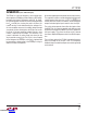
Frequency compensation is provided by the components
tied to the V
C
pin, as shown in Figure 1. Generally a capaci-
tor (C
C
) and a resistor (R
C
) in series to ground are used.
In addition, there may be lower value capacitor in parallel.
This capacitor (C
F
) is not part of the loop compensation
but is used to fi lter noise at the switching frequency, and
is required only if a phase-lead capacitor is used or if the
output capacitor has high ESR. An alternative to using
external compensation components is to use the internal
RC network by tying the COMP pin to the V
C
pin. This re-
duces component count but does not provide the optimum
transient response when the output capacitor value is high,
and the circuit may not be stable when the output capacitor
value is low. If the internal compensation network is not
used, tie COMP to ground or leave it fl oating.
Loop compensation determines the stability and transient
performance. Designing the compensation network is a bit
Figure 1. Model for Loop Response
Table 2. Capacitor Vendors
VENDOR PHONE URL PART SERIES COMMENTS
Panasonic (714) 373-7366 www.panasonic.com Ceramic,
Polymer,
Tantalum
EEF Series
Kemet (864) 963-6300 www.kemet.com Ceramic,
Tantalum T494, T495
Sanyo (408) 749-9714 www.sanyovideo.com Ceramic,
Polymer,
Tantalum
POSCAP
Murata (404) 436-1300 www.murata.com Ceramic
AVX www.avxcorp.com Ceramic,
Tantalum TPS Series
Taiyo Yuden (864) 963-6300 www.taiyo-yuden.com Ceramic
–
+
1.2V
SW
V
C
COMP GND
50k
600k
150pF
LT1936
1936 F01
R1
OUTPUT
ESR
C
F
C
C
R
C
ERROR
AMPLIFIER
FB
R2
C1
C1
CURRENT MODE
POWER STAGE
g
m
= 2mho
g
m
=
250μmho
+
POLYMER
OR
TANTALUM
CERAMIC
C
PL
Downloaded from Arrow.com.Downloaded from Arrow.com.Downloaded from Arrow.com.Downloaded from Arrow.com.Downloaded from Arrow.com.Downloaded from Arrow.com.Downloaded from Arrow.com.Downloaded from Arrow.com.Downloaded from Arrow.com.Downloaded from Arrow.com.