
User's Manual Part 2

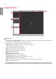


Table Of Contents
- SAFETY PRECAUTION
- Safety Information
- Information for Environmental Preservation
- Safety Information
- Battery Installation
- Specification of each part
- Dimension (unit: mm/inch)
- Environmental Requirement
- INSTALLING CALIBRATION SOFTWARE
- Connection Types
- CALIBRATION SOFTWARE
- Usage
- Service Manual
- Maintenance
- TROUBLESHOOTING
- Solution for firewall block
- Supplement. Wireless AP Set Up Instruction (Model : Cisco Linksys EA9200)

ENGLISH
83
2
Navigator
• The Navigator shows the entire area of the acquired image and indicates the zoomed in/out area.
• The red rectangle in the Navigator indicates the area shown in the Image Viewer.
• Clicking a position in the Navigator moves the red rectangle to the position and displays the area in the Image Viewer.
3
Histogram
• Histogram of the acquired image is shown here.
• Window/Level can be adjusted for better image distinction.
• Use the <> buttons or the scroll bars below the Histogram graph to adjust window/level.
• Click the Reset button to restore the default values.
4
Reference Point
• When you click a position inside the Image Viewer, a reference point is specified, and the coordinates and pixel value
of the reference point are shown at the top. You can also move the reference point by entering the X and Y values
manually.
- Since reference point coordinates are numbers, only numeric values can be entered.
5
Bad Pixel Map Analysis
• Displays the results of bad line and bad pixel class analysis based on the Bad Pixel Map after calibration.