
User's Manual Part 2


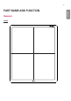
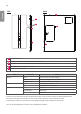


Table Of Contents
- SAFETY PRECAUTION
- Safety Information
- Information for Environmental Preservation
- Safety Information
- Battery Installation
- Specification of each part
- Dimension (unit: mm/inch)
- Environmental Requirement
- INSTALLING CALIBRATION SOFTWARE
- Connection Types
- CALIBRATION SOFTWARE
- Usage
- Service Manual
- Maintenance
- TROUBLESHOOTING
- Solution for firewall block
- Supplement. Wireless AP Set Up Instruction (Model : Cisco Linksys EA9200)

ENGLISH
60
Control Box
255
109.8
125
1
255
109.8
125
7
5
2
3
6
4
1
LED POWER Green Power normal operation
Off Power off (AC power cord no connection or Power error.)
Ethernet Green Ethernet normal operation
Off Ethernet disconnected.
Ready Green Ready signal from X-ray generator is active.
Off Ready signal from X-ray generator is inactive.
Orange blink Error
Exposure Orange Exposure signal from X-ray generator is active.
Off Exposure signal from X-ray generator is inactive.
Orange blink Error
2
DXD 1 Connecting the Control Box and the detector A.
This connector supply power (24 V 2.1 A) to the detector, transmits X-ray
synchronization signals and Ethernet image data.
3
DXD 2 24 V 2.1 A, Trigger signals, Ethernet data for Detector B
Control Box supports 2 Detector connection.
Usage is, one is for bucky stand, the other is for table(bed).
Generally, X-ray room of hospital installs 2 detectors, bucky stand and table type, it's for more
convinient and efficient working environment.
These 2 detectors are not operated simutaniously, control box selects the operating detector
by AWS command.
4
AC-IN Connects AC power cord
5
Ethernet Ethernet port to transmit image/command between the detector and PC.
6
Sync This is to synchronize the detector and X-ray generator.
7
Fuse T4L 250V