
User's Manual


Updated
2008-09-08
File
LEO2 Platform Hardware Manual
Rev.
V1.0
LGE Proprietary iii MCTR Lab.
CONTENTS 1
1. Introduction............................................................................................................................... 1 2
1.1 Scope ..................................................................................................................................... 1 3
1.2 Terminology............................................................................................................................ 1 4
1.3 Trademark List........................................................................................................................ 1 5
1.4 Special Mark........................................................................................................................... 1 6
2. Features and top level diagram ................................................................................................. 2 7
2.1 Features ................................................................................................................................. 2 8
2.2 Photograph of the LEO2-A platform board............................................................................... 2 9
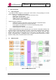
2.3 Top level block diagram .......................................................................................................... 3 10
2.4 Placement map....................................................................................................................... 3 11
3. Block description....................................................................................................................... 4 12
3.1 FPGA subsystem .................................................................................................................... 4 13
3.2 ARM subsystem...................................................................................................................... 4 14
3.3 Debugger Interface ................................................................................................................. 5 15
3.4 RF Interface............................................................................................................................ 6 16
3.5 Reference Clock ..................................................................................................................... 7 17
3.6 Reset ...................................................................................................................................... 8 18
3.7 Application interface................................................................................................................ 8 19
3.8 Power Supplies....................................................................................................................... 9 20
4. DIP switch, LED and logic probing connector ............................................................................ 9 21
4.1 ARM Processor debugging configuration switch setting........................................................... 9 22
4.2 General purpose LED indication........................................................................................... 10 23
4.3 Logic probing connector....................................................................................................... 11 24
5. Description of Smart antenna and beam forming modes if applicable ..................................... 12 25
6. Reference............................................................................................................................ 123 26
27