
User guide


2Introduction
2.6 Conventions used for input/output identifiers
28
Lenze · 9400 function library · Reference manual · DMS 6.7 EN · 08/2014 · TD05
_ _ _ _ _ _ _ _ _ _ _ _ _ _ _ _ _ _ _ _ _ _ _ _ _ _ _ _ _ _ _ _ _ _ _ _ _ _ _ _ _ _ _ _ _ _ _ _ _ _ _ _ _ _ _ _ _ _ _ _ _ _ _ _
Signal type entry
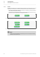
In general, it is possible to assign a certain signal type to the inputs and outputs of the Lenze func-
tion blocks. There are e.g. digital, scaled, position, acceleration and speed signals.
• A corresponding ending (preceded by an underscore) is added to the identifier of the correspon-
ding input/output to indicate the signal type.
• An overview of the different signal types and their scaling is provided in the following subchap-
ter "Signal types & scaling
". ( 29)
Signal type entry Meaning Resolution Value range
_a Scaled 16 bits ± 199.99 %
_n Scaled 32 bits ± 200.00 %
_v Speed 16 bits ± 30000.0 rpm
_s Speed 32 bits ± 480000.0 rpm
_p Position/angle 32 bits -2
31
... 2
31
-1 increments*
* As of controller software version V3.0 the resolution of an encoder revolution can be parameterised in C00100
(Lenze setting: 16 bits/encoder revolution).