
User guide


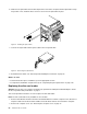


6.Followthefollowingsequencetoremovethefourscrewsthatsecuretheheatsinkandfanassembly
tothesystemboard:
a.Partiallyremovescrew1,thenfullyremovescrew2,andthenfullyremovescrew1.
b.Partiallyremovescrew3,thenfullyremovescrew4,andthenfullyremovescrew3.
Note:Carefullyremovethefourscrewsfromthesystemboardtoavoidanypossibledamagetothe
systemboard.Thefourscrewscannotberemovedfromtheheatsinkandfanassembly.
Figure29.Removingtheheatsinkandfanassembly
7.Liftthefailingheatsinkandfanassemblyoffthesystemboard.
Notes:
•Youmighthavetogentlytwisttheheatsinkandfanassemblytofreeitfromthemicroprocessor.
•Donottouchthethermalgreasewhilehandlingtheheatsinkandfanassembly.
8.Positionthenewheatsinkandfanassemblyonthesystemboardsothatthefourscrewsarealigned
withtheholesonthesystemboard.
Note:Positionthenewheatsinkandfanassemblysothattheheatsinkandfanassemblycableis
towardthemicroprocessorfanconnectoronthesystemboard.
9.Followthefollowingsequencetoinstallthefourscrewstosecurethenewheatsinkandfanassembly.
Donotover-tightenthescrews.
a.Partiallytightenscrew1,thenfullytightenscrew2,andthenfullytightenscrew1.
b.Partiallytightenscrew3,thenfullytightenscrew4,andthenfullytightenscrew3.
10.Connecttheheatsinkandfanassemblycabletothemicroprocessorfanconnectoronthesystem
board.See“Locatingpartsonthesystemboard”onpage6.
Whattodonext:
•Toworkwithanotherpieceofhardware,gototheappropriatesection.
Chapter9.Installingorreplacinghardware87