
User's Manual


UtiliNet® PCMCIA IWR Card User Guide 2/2/2007
Page 17 of 23
PROPRIETARY INFORMATION NOTICE:
THIS DOCUMENT CONTAINS TRADE SECRETS AND CONFIDENTIAL INFORMATION OF CELLNET AND SHALL NOT BE DUPLICATED IN
WHOLE OR IN PART OR USED OR DISCLOSED FOR ANY PURPOSE OTHER THAN THAT APPROVED BY CELLNET.
© Cellnet 2007. All rights reserved.
Noise Floor Factor
One of the factors that make the 800 to 900 MHz frequency band so attractive is the relatively low equivalent noise
temperature of man-made noise. For a noisy business environment, this has been estimated to be 87 K at 915 MHz.
Relative to an ambient antenna noise temperature of 298K, this translates to a noise floor increase of 1.2 dB. Thus, we will
allocate 1 dB (rounded to the nearest dB) of the link budget to overcoming man-made noise.
Multipath Fade Factor
For most receive signal measurements, slight changes of antenna location (on the order of 1 wavelength), or measurements
at different times, will show a short-term variance of received signal level. This is generally due to multipath. An
allowance of approximately 8 dB should be made on most radio links at 915 MHz. This is because the difference between
a median received signal level and a multipath null does not exceed 8 dB for about 80% of the measurements you could
make. This factor can be reduced by one or more diversity schemes that are available. All Cellnet spread-spectrum radios
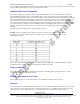
inherently employ frequency diversity; however, it doesn’t hurt to be conservative and still include this factor. Tabulated
below are 915 MHz multipath factors for other values of percent coverage. This factor varies slightly (1 to 3 dB) for
various types of environments. Values shown are for 915 MHz urban area, small city.
Margin of Safety
Radio systems are usually not designed to operate precisely at threshold, or even at threshold plus the multipath factor.
Usually they are designed with some extra margin. This is called a margin of safety, and is used to account for long-term
variance in the received signal level. A value of 0 to 35 dB is suggested—the actual number depends on how conservative
you are. You will use 5 dB for this example. If the actual path could be held constant at the receiver threshold, and never
varied, you would see data success rates of at least 90%. This is because at receiver threshold, the receiver provides no
more than 10% packet error rate. Since the data link layer of the radio software only passes good packets and blocks bad
packets, the data success rate would be 100% minus 10%, or 90%. In practice, however, received signal levels vary
substantially. Rx signal levels cannot be precisely predicted. In fact, Rx signal levels vary due to such factors as vehicular
air traffic, precipitation and air temp changes, wind movement of trees and antennas, tree growth, city growth, and
population expansion. Systems are usually designed with an additional margin of safety to overcome these and other
variances for the next several years of operation.
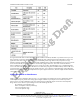
Summary
For this example, the link budget is calculated as shown. Note that losses and margin of safety are shown as negative
numbers, since they subtract from link budget.
Table 3.3 Example Link Budget Calculation