
User's Manual


UtiliNet® PCMCIA IWR Card User Guide 2/2/2007
Page 16 of 23
PROPRIETARY INFORMATION NOTICE:
THIS DOCUMENT CONTAINS TRADE SECRETS AND CONFIDENTIAL INFORMATION OF CELLNET AND SHALL NOT BE DUPLICATED IN
WHOLE OR IN PART OR USED OR DISCLOSED FOR ANY PURPOSE OTHER THAN THAT APPROVED BY CELLNET.
© Cellnet 2007. All rights reserved.
calculated differently, using dipole antennas instead of isotropic antennas. Such is not the case here, but if it were, the 2 dB
factors for dBd to dBi antenna gain conversions would not be included.
Additional Path Loss Attenuation
For non-line-of-sight paths, an additional factor must be included that corrects for variables such as terrain, obstacles
(including buildings), foliage, people, or antenna height. This is a factor to take into account for the installation and the
path, as it is today. This factor can be derived from the works of many individuals who have studied radio propagation and
derived mathematical models: Okumura/Hata, Longley/Rice, Lee, and others. There are various CAD tools available that
are based on these measurements or algorithms. Note that some of these CAD tools will only return the total path loss
factor. Other CAD tools perform the entire link budget analysis. For our discussion, let’s continue to consider the RF path
as a sum of the freespace path loss term and an additional path loss term. Height of both antennas, the type of environment
along the path, distance, and other parameters can determine this factor. Typically, this factor ranges from 5
to 40 dB.
This factor, plus the free space path loss, gives total median path loss.
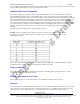
Example: Assume a path that is 5 miles long. One antenna is on a hill or water tank 300 ft. higher than the
surrounding area. The other antenna is on a 30 ft. support structure, for example on the rooftop of a 1 story
building. Except for the
hill or water tank, the terrain is considered relatively flat. The path loss adder term is -10 dB at 915 MHz, according to
the Okumura/Hata propagation prediction method using the suburban area model.
Receiver Antenna
The previously mentioned antenna considerations also apply here, including possible ground plane effects. For this
example, this is (again) a “3 dB omni-directional.”
Receiver Transmission Line Loss
The principles and goals here are the same as those for the Transmitter Transmission Line Loss term.
Receiver
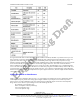
Receive sensitivity for the UtiliNet product line is typically -107 to -112 dBm. Automated production tests are performed
on all deliverable radios at various frequencies, and with signal levels down to -104 dBm. For this example, assume the
receiver sensitivity is -107 dBm. This is a safe, conservative estimate for current production radio sensitivity.